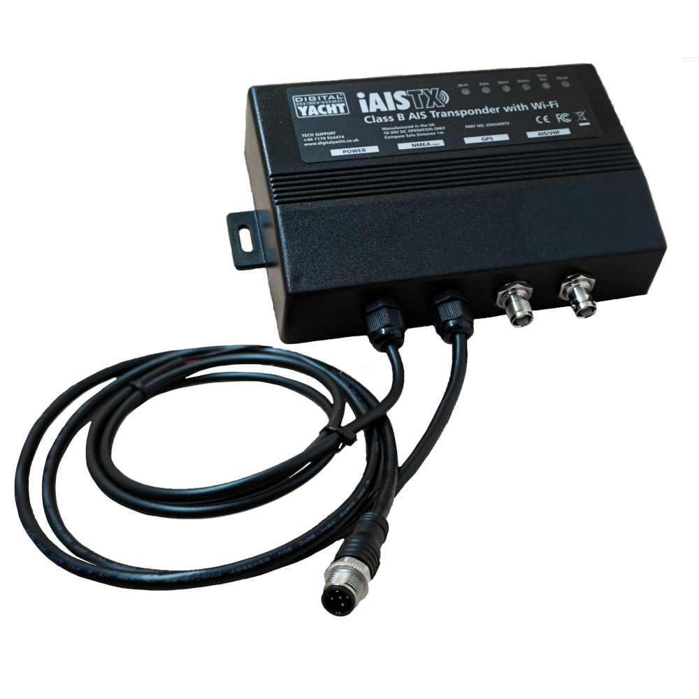
Description
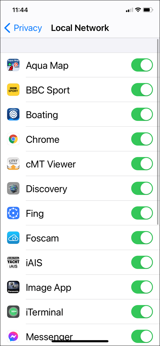
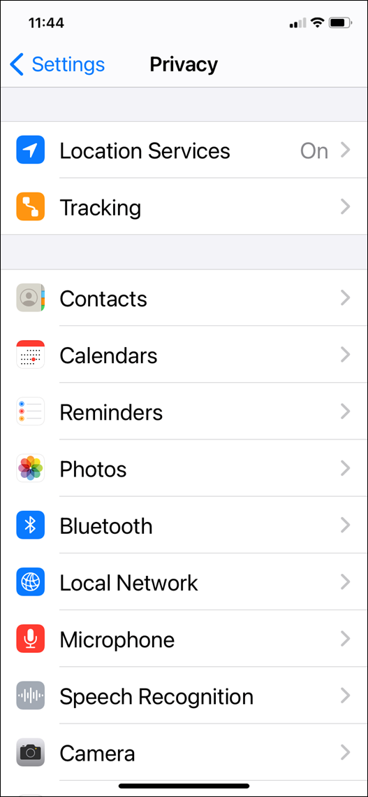
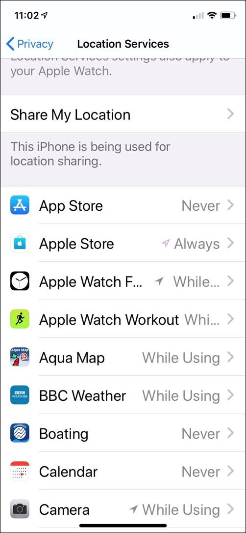
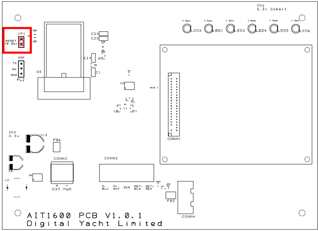
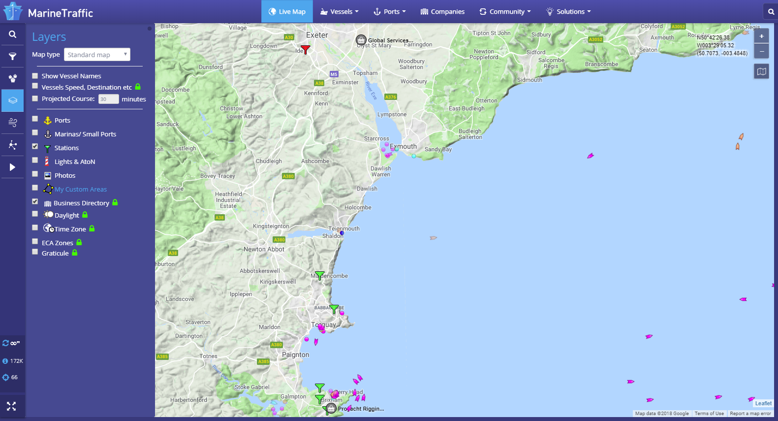
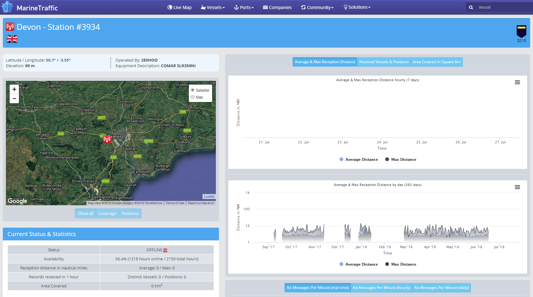
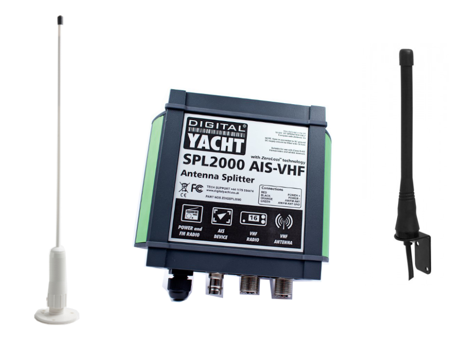
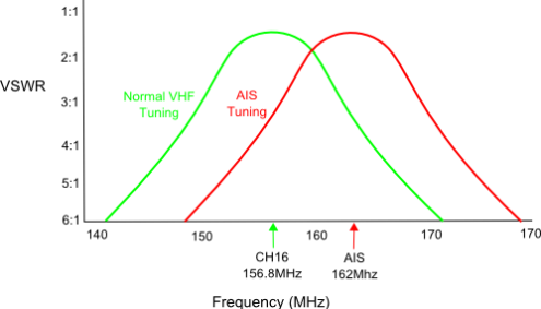
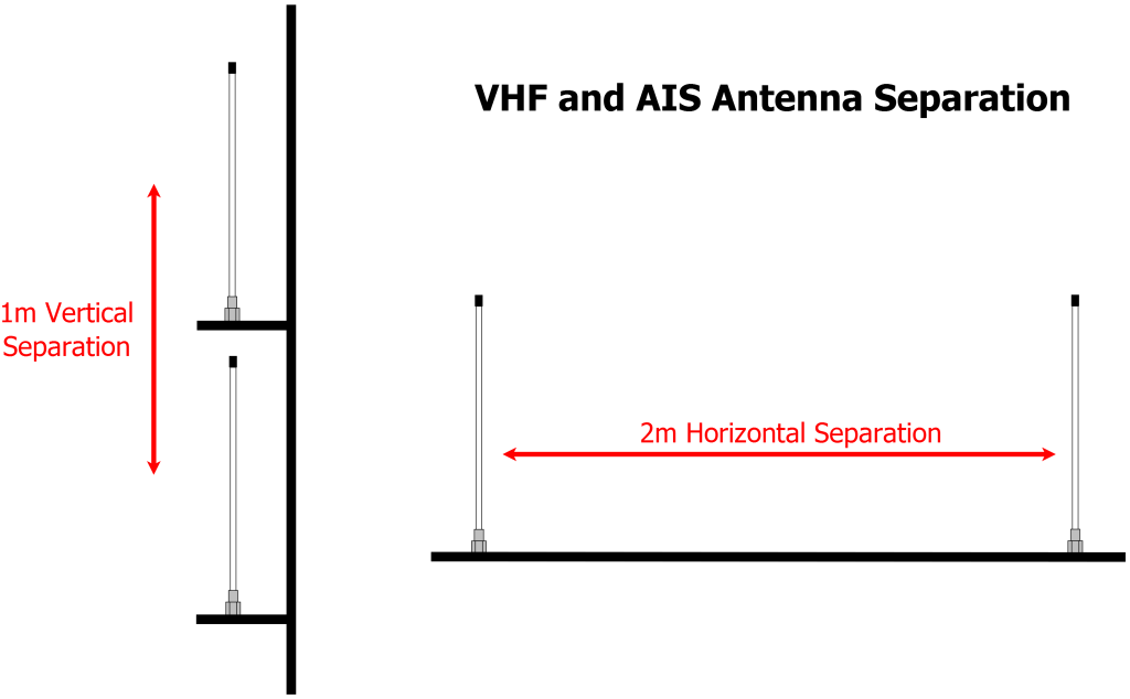
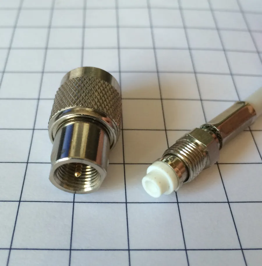
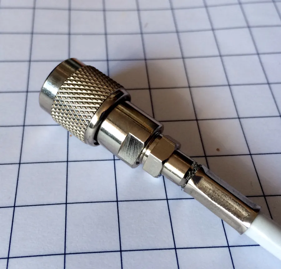
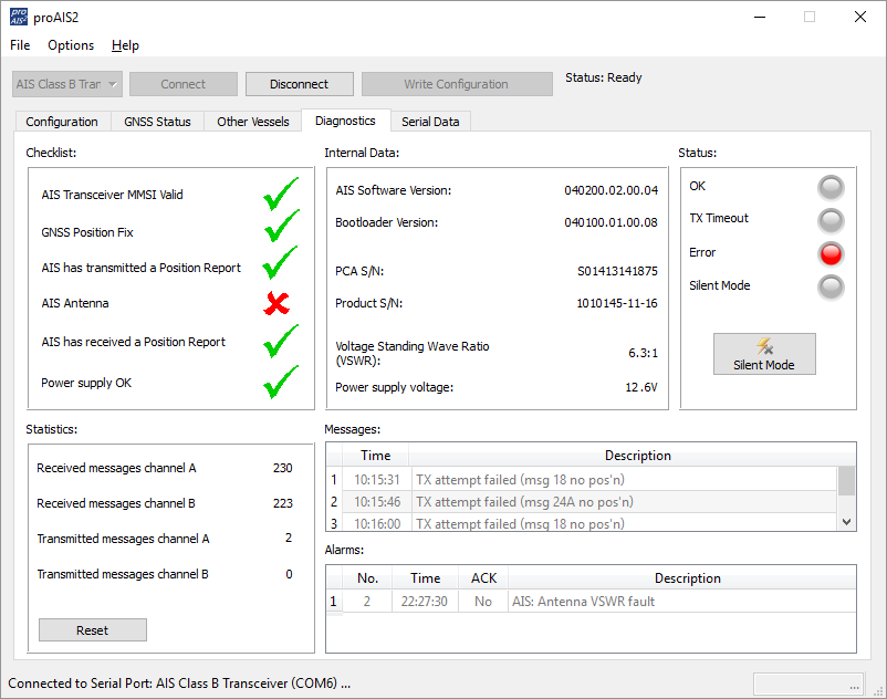
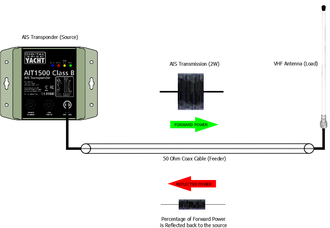
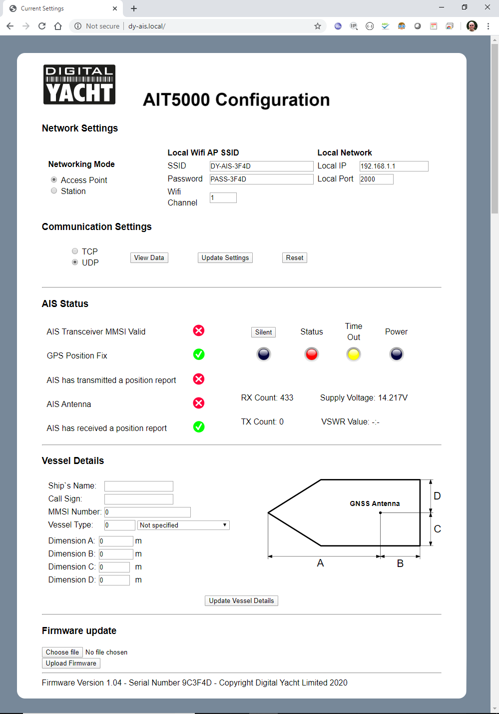
To check the TCP and UDP connections with another App to rule out that there may be an issue with the Navionics Boating App, use this – TCP UDP Server & Client on the Play Store which is a really good test tool for Android…. I setup a TCP Client and a UDP Server for NAVLink2/WLN10SM etc. and started them running (one at a time) and just watched the raw NMEA 0183 data coming in. There should be no crashes or stoppages of data. If this is all working fine but you’re still having connection issues, then please contact our support team. In the proAIS2 Diagnostics page, you will often see DSC and TX Attempt failed warnings displayed. These warnings are referring to normal AIS transponder behaviour and here is some more info on these messages… The RX 1 / RX 2 DSC start / Stop message is a completely normal message, indicating when one of the AIS receivers has started/stopped a DSC channel management listening period. Class B equipment is required to listen to channel 70 periodically (at specific times defined in the standards) for DSC channel management commands. As Class B lacks the third receiver necessary to do this full time it is achieved by occasionally switching an AIS receiver to this channel. TX attempt failed (Msg 18) and CP Busy messages are often seen, as Class B AIS is a ‘carrier sense’ system. It has to find a free slot to transmit in by listening just before transmission to check the slot is empty.When a transmission is scheduled a block of 10 potential slots is selected. It will attempt to transmit in the first of these slots. If the slot is busy the ‘CP busy’ (meaning ‘candidate position busy’) message will be output. It will then try again in the next slot, and so on for the 10 slot block. It is quite normal to see ‘CP busy’ messages in an area where other AIS vessels are operating. It simply means the first slot selected was busy. 99% of the time the transmission will be successful in one of the other 9 slots. So long as the indicator remains green transmissions are occurring on schedule. If transmissions can’t be made because the AIS environment is simply too busy then the indicator will turn amber (this is incredibly rare – we have never witnessed it outside of test conditions). In summary these messages are normal and can be ignored if the “Power” LED indicator is green. NOTE – these conditions are not shown as an error or alarm in proAIS2 , just in the ‘messages’ box. Anything in the ‘messages’ box is just for info and not a fault or alarm; those are shown in the ‘Alarms’ box. A couple users have seen that the Supply Voltage on the Status Page is showing as around 8v but when they disconnect and test are getting 12v +. The Green Power LED is a very good indicator that the AIT5000 transponder is working correctly. The Status web page shows the default values and indicates that there is no NMEA communication between the transponder and the web browser. The most common causes of this are:- Please check that neither of these two issues are causing your problem. If you are still experiencing an issue, please contact our Support Team by creating a ticket here. The WiFi icon on the iPhone not showing is the wireless network you are connected to, does not have an internet connection. This is a fairly recent change. On earlier versions of iOS this icon was always displayed and shows a user if they are using WiFi or 4G connection for internet, which is an important thing to know. Most users will be connected to normal home or office wireless networks that have an internet connection. Only a small percentage of iPhone users will have an iAISTX or similar wireless device that does not have internet connection, so having a feature for the majority won the day. The weak security message is also a recent change, as Apple are pushing all of their users to move to the latest and most secure WPA3 security. The reality is that WPA2 is still very secure and still used on the majority of wireless networks, so it is nothing to be worried about. Even if a hacker did manage to crack your iAISTX, all they would gain is the location of all the AIS equipped vessels around you – not any sensitive banking or personal info. In the original International Product Specification for Class B AIS Transponders, it was dictated that they should be “stand alone” systems that did not require any input from other devices. For this reason, you will not find any AIS Class B transponders that can take their position input from an external NMEA 0183 or NMEA 2000 GPS sensor. I am afraid that you will need to use the supplied GPS antenna with your iAISTX, but if your boat has a GRP hull, then you might be able to install the GPS antenna inside the hull and not go to all the trouble of routing it externally. Just find a suitable location and use the GPS signal strength display on the iAISTX’s web interface to check that you are getting good reception, before finally bolting it down. All Class B and Class B+ AIS transponders can transmit the True Heading of the vessel as part of the dynamic data they transmit to other vessels; MMSI Number, Position, COG, SOG, etc. If received most charting systems will plot the AIS target with both the COG and True Heading vector displayed, useful when the vessel is stationary and COG becomes unstable/inaccurate. Our AIT2500 and AIT5000 units can receive the True Heading (HDT or THS sentences) data via their Low Speed NMEA 0183 Input (Yellow+ and Green- wires) or via PGN#127250 Vessel Heading on NMEA 2000. However, not all NMEA 2000 systems will transmit True Heading and in some cases they transmit a wrong value or just a fixed 000º. This results in the AIS target being plotted with a very strange heading vector or the boat appearing to be moving side-ways or backwards. If this happens and you cannot correct or suppress the True Heading value on the NMEA 2000 network, then you can stop the AIT2500/AIT5000 from receiving True Heading over NMEA 2000, by following the procedure below…. Using the proAIS2 software, go to the Serial Data tab and then copy and paste the following commands in to the box at the bottom of the page and click the “Send” button (see image below). ….if the command was successfully received and actioned, you should see Transponder respond with… A flashing RED Status LED indicates a high VSWR reading or potentially a Power Amplifier fault. For the flashing RED Status LED issue, with the 12v power turned off to the AIS Transponder, I would visually inspect the BNC antenna connector on the AIS and make sure there are no signs of connector damage. Then connect up whichever VHF antenna you have the most confidence in. Now power ON the AIS Transponder and immediately join its wireless network and bring up the web interface before the unit has got a GPS position fix and tried to transmit or use ProAIS2 if your AIS transponder don’t have a web interface. Now watch the VSWR reading and see what value is displayed after the first couple of transmissions. If it is greater than 5:1, then it has a high VSWR and will soon start to flash the RED Status LED. The most common cause is the VHF antenna and connections, but if you are confident that they are all fine, then it must be the unit itself and we will need to get it back for warranty repair. When we get reports like this, it invariably turns out to be Chart Plotter or Application that has a problem – usually software related. The reason for this, is that AIS units do not differentiate between different types of AIS messages; either the regular dynamic ones that include the MMSI number and the position/course/speed of the vessel or the more infrequently transmitted static ones that include the MMSI number, name, dimensions, boat type, etc. and in the case of Class A vessels the voyage data that includes navigation state, destination, ETA, etc. An AIS unit either receives all of the messages or none. In theory, if the AIS was getting poor reception and missing some messages then because a boat might send 10 dynamic messages for every 1 static message, you are more likely to see the boat without the static data, but it would be random and some boats would have their names. The application only needs to receive the static data once for a target, and then it is in its temporary AIS database for the duration that the application is running. As I mentioned, the Chart Plotter or Application maintains its own AIS database where it ties together the MMSI numbers in the dynamic and static messages and builds up an AIS target list where every boat should (within 6 minutes) have a name, dimensions, boat type, etc. The static messages are longer than the dynamic ones and might be split across a couple of UDP network packets. You could try setting the iAISTX to operate in TCP mode and then setup a new Device on the Navionics App; TCP mode, Host = 192.168.1.1 and Port = 2000. TCP mode is a guaranteed delivery protocol with error checking, packet sorting and re-transmit functionality, that ensures all network packets are always fully received. The downside, is that it is a one device protocol so you cannot have more than one device receiving the data at a time. This reset procedure just resets the AIT5000 unit’s wireless interface and does not reset the MMSI number, which can only be carried out by an authorised dealer/distributor. With the AIT5000 unit fully powered up, locate the reset button, which is a small push button next to the wireless antenna. Press and hold this push button for > 10 seconds (recommend 15 seconds to be sure). When you release, you should see the Wi-Fi and Data LEDs change flashing sequence slightly as the unit resets and reboots. Once the AIT5000 has rebooted, all of the wireless and web settings will be back to the factory defaults – as detailed in the user manual. You should now be able to see the AIT5000-xxxx wireless network again. Try to get one of your devices to connect and stay connected to the AIT5000 Wi-Fi connection. If you think that your AIS transponder is not transmitting your position then this procedure might help you. The first step is to check if your AIS transponder is actually transmitting. If you are then sure that your AIS transponder is not transmitting then the next part explains you the factors to check. Using the proAIS2 configuration software or the iAISTX/AIT5000 web interface allows you to see if the GPS position is OK. You can monitor the AIS reception of other vessels. As well as ensure that there are no errors or alarms. However, if you are new to AIS, there is always that nagging doubt as to whether other vessels are seeing you. The best test of a Class B transponder is to ask someone else in your marina, who has AIS, to check that they are receiving you on their system. If your vessel is stationary, then a transponder will only transmit every 3 minutes. This increases to every 30 seconds when your speed over the ground (SOG) is greater than 2 knots. Therefore, do allow some time for them to detect you. Also when they first receive your transmission, the only data they will see is your position, speed, course and MMSI number. It can take up to 6 minutes to receive your “Static Data” (boat name, call sign, vessel type, dimensions, etc.). This is normal and is the way the AIS system regulates the amount of data being transmitted. The other increasingly common method of testing an AIS transponder is to look on one of the online “live” AIS websites and the most popular of the free services is MarineTraffic.com However, it is important for you to be aware of the limitations of these online sites. As a result, do not assume that you will always be picked up by them. Each of the different online services are only as good as their network of AIS receiving stations. In many cases enthusiasts/volunteers operate these. In some areas the coverage is great but there are definitely “holes” in coverage. If you are now sure that your AIS transponder is not transmitting then you should follow the following steps. You must use ProAIS2 for your AIT1500, AIT2000, AIT2500, AIT3000 or Nomad. However, for the iAISTX, iAISTX Plus or AIT5000, you must use the built-in web interface. With proAIS2’s diagnostics tab or the iAISTX/AIT5000 web interface, you can check if an AIS transponder has an issue or not. Without a good GPS fix, an AIS transponder cannot transmit correctly your position. By going to the GPS Status tab in ProAIS2, you can see the GPS reception. If you have one of our AIS transponder with built-in GPS antenna, then you should consider installing a GPS booster (for more information, click here). If you have an external GPS antenna then make sure that the connectors are correctly tight and also that the antenna is outside and has a clear view over the sky. In the Diagnostics Tab in ProAIS2 or within the iAISTX/AIT5000 web interface, you can see the VSWR ratio. The VSWR ratio is explained in the FAQs. If your VSWR ratio is above 3, then you must check the VHF antenna connectors and the cable. If possible, use another VHF aerial to check if the AIS transmits better. In the Configuration Tab in ProAIS2, you must make sure that all the boat details have been added (MMSI, VHF Call Sign, Name, Dimensions, etc.) You can send us via email a screenshot of the ProAIS2 diagnostics tab or your iAISTX/AIT5000 web interface, we will then let you know whether the product works well or not. This video might also help you out: A coax cable has an inner wire and then the braided shield and a quick and easy way is just to strip the cable back and solder or join using terminal block the Inner wire to the Orange wire and the Outer shield to the Green wire. However, if you want to make a nicer, more robust solution, you could get one of these… https://www.adafruit.com/product/2889 and one of these… Then the Orange wire would go in the + screw terminal and the Green in the – screw terminal. The BNC connector would be crimped on to the coax cable and you end up with a much more longer lasting connection. If you encounter an issue with AIS showing on your display (navigation software or chart Plotter) then you should follow this procedure. If you cannot display AIS targets on your Chart Plotter or VHF radio, then follow this: If you cannot display AIS targets on your navigation software or app then follow this: If you don’t have a good range, we suggest you testing with another VHF aerial to check if you have a better range. If you don’t receive the NMEA data on your iPad or iPhone, then you must follow this procedure: 1- Close all apps in the background or restart your device. Always a good idea to shut down your iPad/iPhone device and then power it back up again, as this will close all background apps and ensure all of the right services are running. For more information: https://digitalyacht.net/2018/07/27/background-apps-stopping-wireless-nmea-transmission/ 2- Local Network Settings If you are using iOS 14 or higher, make sure the “Local Network” privacy settings are enabled for the app they want to use…. Go to Settings>Privacy>Local Network and make sure that the App is in the list and enabled…. 3 – UDP or TCP? Check what mode/protocol our product is set to, TCP or UDP (check product manual) and ensure that you set the same type of connection in the App. If the device is set to UDP and you try to use TCP in the App it will not work, both the device and app must be set to the same mode/protocol TCP or UDP. For TCP connections you need to enter an IP address of 192.168.1.1 and Port 2000, while for UDP you need to enter 0.0.0.0 and Port 2000, or if this fails try 192.168.1.1 4- App configured? You must make sure that your app is configured. You should look at our section How to Configure Apps & Software to find out how to configure your navigation app. 5- GPS Settings If you want the app to use the GPS data from the wireless connection, then go to Settings>Privacy>Location Services, on your iOS device and set the App to “Never” which will force the App to use the GPS position from the wireless connection, rather than try and use its internal GPS or even worse “Assisted GPS” if it is a Wi-Fi Only iPad. This reset procedure just resets the iAISTX unit’s wireless interface and does not reset the MMSI number, which can only be carried out by an authorised dealer/distributor. To reset the iAIS TX, you must open the product case by removing the 4 screws from the unit. Once the screws have been removed, the base should be carefully disengaged from the top of the case using a small flat blade screwdriver. There are interconnecting cables between the top and bottom of the case, so take care not to separate the two parts completely. There is only one PCB inside and the PCB diagram is shown below with the JP1 connector that you need to short in red… With the unit’s 12/24v DC power on, short the two pins of JP1 for at least 10 seconds (allow 15 seconds to be sure). When you release, you should see the Wi-Fi and Data LEDs change flashing sequence slightly as the unit resets and reboots. Once the iAISTX has rebooted, all of the wireless and web settings will be back to the factory defaults – as detailed in the user manual. You should now be able to see the iAISTX-xxxx wireless network again. Try to get one of your devices to connect and stay connected to the iAISTX Wi-Fi connection. Another nice feature of Marine Traffic, is that you can drill down in to the details of a particular receiving station. Click on the icon of the Station of interest and a summary of the receiving Station’s information will be displayed. By clicking the Green “Details and Statistics” button, you can get a wealth of information about the station, its statistics and “live” AIS target reception list. One of the most common questions we are asked by our AIS customers, is “what antenna should I use for my AIS ?”, so we thought we would post a short article to provide an answer on VHF Antenna Options for AIS. Basically there are two VHF antenna options for AIS; fit a second dedicated VHF antenna a suitable distance from the vessels main VHF antenna. Or alternatively, use the main antenna for both VHF and AIS by fitting a special device called a “Splitter”. Generally our recommendation for yacht owners who want to fit an AIS, is to use a “Zero Loss” splitter like our SPL2000. By utilising the main VHF antenna at the top of the mast, you will definitely get maximum transmit range. Plus the ease of installation often makes it a cheaper option than paying for a second antenna to be installed. However, for power boaters who do not benefit from the height advantage of using the main antenna at the top of the mast. As well as for AIS receiver owners where the splitter can often cost more than the AIS receiver itself. It is often desirable to fit a second VHF antenna. This is particularly apparent if you intend to save money by doing the antenna installation yourself. AIS operates on two dedicated channels within the marine VHF frequency range – 156.0 to 162.025 MHz. The two AIS channels are at the top end of this range namely; 161.975 and 162.025 MHz (channels 87B and 88B). Most VHF antennas are designed to give maximum gain across the whole VHF frequency range centred on Channel 16 (156.8 MHz). Pretty much all of the antenna manufacturers now produce “AIS Tuned” antennas. These have their centre frequency shifted from Channel 16 to 162Mhz (exactly half way between the two AIS frequencies). If you choose to mount your AIS antenna on the stern rail of a yacht or radar arch of a power boat. Then using an “AIS tuned” antenna is a good idea. This will allow you to get an extra bit of gain. Thus compensating for the antenna being effectively at deck level. The graph above shows how the tuning of the antenna to 162MHz gives it an extra boost in VSWR (gain) across the two AIS frequencies. Which ever option you choose, having AIS on your boat will without doubt make your sailing experiences safer. As well as less stressful in poor visibility or when crossing busy shipping lanes. Even a simple receiver with a small whip antenna at deck level is effective. Allowing you to keep informed of what ships are around and which ones you need to keep an eye on. The AIS system works on two channels in the VHF frequency range and in order to receive or transmit AIS information it is necessary for the AIS unit to be connected to a VHF antenna. One option is to fit a VHF splitter such as our SPL2000, which allows both the VHF radio and the AIS to use the boat’s main VHF antenna. The other option is to fit a second VHF antenna which is then just connected to the AIS. Any VHF antenna can be used, although some antennas are “AIS tuned” to get maximum gain on the two AIS channels and also have a BNC type connector fitted (common on AIS units), rather than the traditional PL259 VHF connector. If you decide to fit an additional VHF antenna for the AIS, you want to mount it as high as possible but you should be aware that it cannot be mounted right next to the existing VHF antenna and a certain amount of separation must be maintained to avoid the 25 watts of transmit power from your VHF radio going straight in to the AIS receiver circuitry, potentially damaging it. The diagram below shows the recommended minimum separation of the antennas. Our AIS transponders are supplied with a GPS antenna that has a 10m cable terminated in an FME connector (right hand connector in the above image). These connectors are very slim, not much larger than the coax cable and are much easier to route through the boat. We also supply an FME to TNC adaptor for connecting the cable to the transponder (left hand connector in the above image). Today we were reminded of the importance of ensuring this adaptor is firmly screwed on to the cable, when a US customer reported that their AIT2000 had stopped getting a GPS fix. After using the proAIS2 software to confirm that the GPS signals were very low, we asked the customer to check the GPS antenna connections to the AIT2000 and sure enough found that the FME connector had become loose and was no longer making a good connection. A quick tighten of the FME connector in to the adaptor and the AIT2000 started to get a GPS fix again and the customer could continue their cruise. The nut on the FME connector is 8mm (AF) and the TNC adaptor has two flat indents that are 9.5mm (AF). You can tighten the two connectors quite tightly but avoid using too much force which could damage the connector and cause a different set of problems. The image below shows the FME fully tightened in to the adaptor and there should be about a 1.5mm gap between the FME nut and the collar of the adaptor when properly tightened. Our GV30 combo GPS and VHF antenna also uses FME connectors and is supplied with a TNC and BNC adaptor, which should also be tightened in the same way. Checking the VHF/AIS Antenna, is the most difficult test. As a result, it is the one that we get the most technical support calls about. Therefore, we thought a blog post on the subject would help. It is surprisingly common for yacht owners to install an AIS transponder with an antenna splitter and then find that their “old faithful” VHF antenna at the top of the mast is actually not as good as they thought it was. The reason for this, is that the top of the mast is a pretty hostile place. Over time, the antenna will suffer high levels of salt water and UV exposure, coupled with large temperature swings, vibration, G forces, etc. All of which start to degrade the materials and cabling. Alongside the occasional stepping of the mast, with possibly a through-deck connection or cable join inside the hull. You can see that there are lots of possibilities for the antenna to not be in tip-top condition. All AIS transponders perform a continuous series of self tests, including a VHF antenna test. This is often the first time, in many years, that the VHF antenna at the top of the mast has been tested. Therefore, it is not unusual for some to fail the test. The reality is, that a VHF radio or AIS will happily get some level of reception even if you just connect a wire to it. As a result, you can appear to be receiving AIS data but your transmission is poor. This is due to an old/degraded VHF antenna that has a high Voltage Standing Wave Ratio (VSWR). The VSWR of an AIS transponder, is a measure of the level of standing waves present in the antenna cable (feeder). Standing waves are the signals/power that do not radiate in to the air, by the antenna (load), but reflect back down the cable to the transponder (source). In an ideal world, all of the power sent to the antenna would transmit through the air to other vessels. However, this only happens if the impedance (AC resistance) of the source, feeder and load are identical (50 ohms). This perfect matching of the impedances would result in a VSWR of 1:1. Although in “real life” pleasure boat installations, it is more likely to be between 1.1:1 and 2.5:1. In the diagnostic page of our proAIS2 software, the you can see the VSWR and will update upon every transponder transmission. By keeping an eye on the Transmit Counter you can see when a transmission takes place. You will probably see a slight change (in the decimals) each time the VSWR is measured, which is normal. If you see a bigger fluctuation, this is indicative of a poor connection or water ingress in the antenna cable/connections. If the measured VSWR goes above 5:1, the RED Status LED will illuminate and a VSWR alarm displayed in proAIS2 (see top image). Understanding the importance of having a good VHF antenna, with a low VSWR to get the best possible AIS transponder performance (transmit range) is key. We hope this article helps our customers have a better appreciation of this technology. Once entered and confirmed, the MMSI number on an AIS can only be changed by a technical dealer or by Digital Yacht. This is a government requirement in many countries to ensure the security of the AIS system. If you need your MMSI number reset or changed, we offer a reprogramming service. The cost for this is £65.00/75.00€ + Return Shipping (+VAT – if applicable) If you would like to go ahead with this, please complete and print the following: If you do not have Microsoft Word or a means of editing Word documents, please print and complete this PDF version. Please return the AIS transponder with the printed AIS PROGRAMMING form to the following address: If you’re returning a product from outside the EU, please put a value of GBP £10.00/ USD $14.00 / EUR €12.00 for the product and if requested by the freight company or postal service, use MARINE ELECTRONIC EQUIPMENT as a description and the commodity code 90148000. The reason for return can be Product Service or Return for Repair. Alternatively, the MMSI can be reset by any local NMEA certified/technical marine dealer who will have the cables, programming leads and software to complete. For Nomad and Nomad2 customers, please contact us via our ticketing system. The Wi-Fi will typically footprint a boat up to 25m LOA. Contact us if you need a bigger footprint or have a steel or carbon vessel. Yes! You can program this through the web interface so you just have one Wi-Fi network on board with our product linked directly to your other Wi-Fi network as a client. This is explained in your product manual. This works well as well with Furuno WiFi radar installations. We keep on our blog a list which explains how to configure all the popular navigation apps & software. This list explains how to configure a NMEA connection (UDP/TCP) on the app/software but also how to configure the AIS settings. To see the list, please click here. Up to 7 devices can connect using UDP. TCP/IP is a one to one connection format. PCs, MACs, Android, Linux and iPhone/iPad are all compatible. Our AIS transponders with a built-in web interface create a password protected WiFi network. With your tablet, PC or smartphone, if you scan for wireless networks, you should see a wireless network called “DY-AIS-xxxx” or “IAISTX-XXXX” where xxxx is a four-digit code unique to your AIS transponder. The name of the WiFi networks might change according to the product version. Make your device join this network and you will be asked to enter a password which is “PASS-xxxx” where xxxx is the same four-digit code as in your network name. You can change both the network name and password in the AIS transponder unit’s web interface. For instance, if you have an AIT5000 and the WiFi network name created is DY-AIS-D4B7 then the WiFi network password is: PASS-D4B7 In order to facilitate the use and configuration of our AIS transponders, our new AIS transponders now have a built-in web interface. This is the case for the iAISTX, iAISTX Plus and AIT5000 (since March 2020). These devices create a WiFi network on board and configure themselves by connecting to WiFi. The configuration of the transponder can therefore be done through a computer, a tablet or even a smartphone and most importantly, no software is required. Our other transponders can only be configured through a computer by connecting the USB and downloading a specific software (ProAIS2). After installing and powering the device, here is the procedure to configure the AIS transponder through the web interface. The screenshots below use our old built-in web interface version. You need to connect to the WiFi network created by the AIS transponder (network name: DY-AIS-xxxx) . If the WiFi network has a password, then the password is: PASS-xxxx (xxxx is a 4-digit code unique to your device and is the same as the 4 digits on the WiFi network name). Then, open a web browser (Safari, Chrome, Firefox, Edge, etc.) and either enter the IP address of the transpondeur… http://192.168.1.1 …or if your device supports Bonjour/mDNS you can enter the following URL… http://dy-ais.local This is the section in which you enter the MMSI and Static data to program the transpondeur. The MMSI number can only be programmed once, so particular care should be taken to check that it is correctly typed in. All other data can be changed at any time. You need to enter your boat dimensions and an approximative location of the GNSS antenna. Once you are happy that all your boat’s static data has been entered correctly, remembering to double check the MMSI number, click the “Update Vessel Details” button and the details will be stored in the AIS unit. By default, the AIS transponder is in “Access Point” mode, that means it creates its own password protected wireless network and automatically provides network settings to any device that connects to it (via DHCP). You can change the default network name and password, if required, and the wireless channel that the unit uses (Channel 1 by default). For the rest of the network settings, we recommend that you do not change anything. If you want to merge the AIS’s WiFi to an existing WiFi network on board, please read the unit manual. Once everything is configured for the network settings, click on “Update Settings” button and the unit will save the new settings and restart (it takes about 30 sec). By default, the AIS transponder is in “Access Point” mode, that means it creates its own password protected wireless network and automatically provides network settings to any device that connects to it (via DHCP). You can change the default network name and password, if required, and the wireless channel that the unit uses (Channel 1 by default). For the rest of the network settings, we recommend that you do not change anything. If you want to merge the AIS’s WiFi to an existing WiFi network on board, please read the unit manual which you can download from here. Once everything is configured for the network settings, click on “Update Settings” button and the unit will save the new settings and restart (it takes about 30 sec). Thanks to the web interface, you can also display the NMEA 0183 frames broadcast by the WiFi of the AIS transponder. You have to click on the “View data” button at the top of the web interface. If you have connected instruments to the NMEA 0183 input of the AIT5000, you will also be able to see the data of these instruments in this page. At the bottom of the web interface, you can update the product when an update is available. Simply select the file in your computer or tablet with “Choose File” and then click on “Upload Firmware”. If you need to disable the GNSS PGNs that the AIT2500/AIT5000 outputs then this is the procedure to follow…. Using the proAIS2 software, go to the Serial Data tab and then copy and paste the following commands in to the box at the bottom of the page and click the “Send” button (see image below). ….if the command was successfully received and actioned, you should see Transponder respond with… This video will show you how to install our AIT5000 Class B+ AIS Transponder for NMEA 0183 & NMEA 2000 based systems. To configure the AIT5000, you need to configure the AIT5000 with its built-in web interface.Testing UDP and TCP connections with a Testing App
DSC and TX Warning Messages in proAIS2
AIT5000 Voltage Problem
Why does my iPhone/iPad show “Weak Security” or no WiFi icon?
Can I use an external GPS antenna for my AIS Transponder, or do I have to use the supplied antenna?
AIT2500/AIT5000 – Disable NMEA 2000 Heading Reception

$PSMT,0,3,0x2C75B2FA,1,n2kignss 0,0*13
$PSMT,0,3,0x2C75B2FA,1,n2kignss 1,0*12
Red Status LED flashing on my AIS transponder
AIS is not displaying boats’ names
How to manually reset an AIT5000
My AIS Transponder is not transmitting
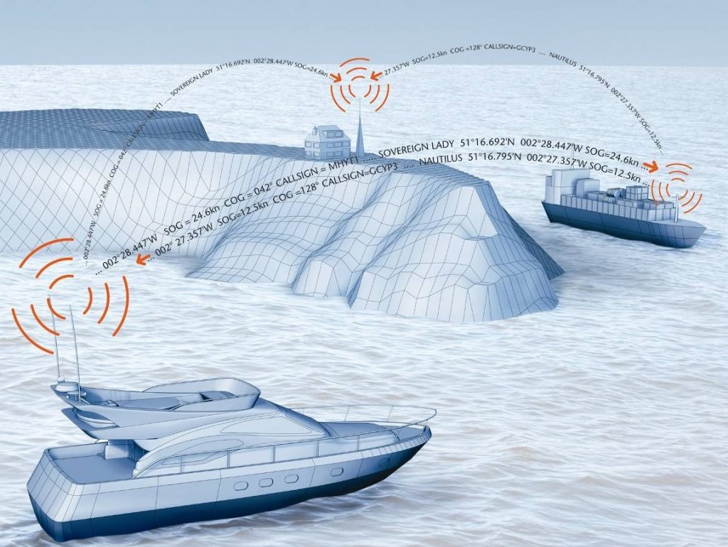
1 – Check if your AIS is transmitting or not
With ProAIS2 or iAISTX/AIT5000 Web Interface
Check with a local AIS Receiver/Transponder
Check with MarineTraffic, Vessel Finders, etc.
2 – Find out the reasons why your AIS is not transmitting
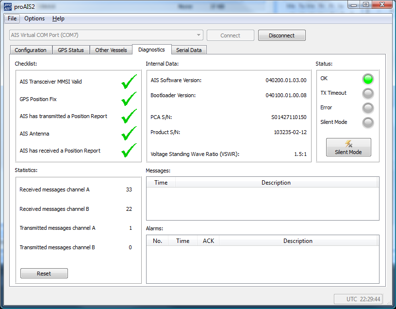
A- Check if your AIS receives a good GPS position.
B- Check the VHF antenna
C – Check that all the data have been entered
Connecting FM Radio to the VHF Splitter
I cannot display AIS targets
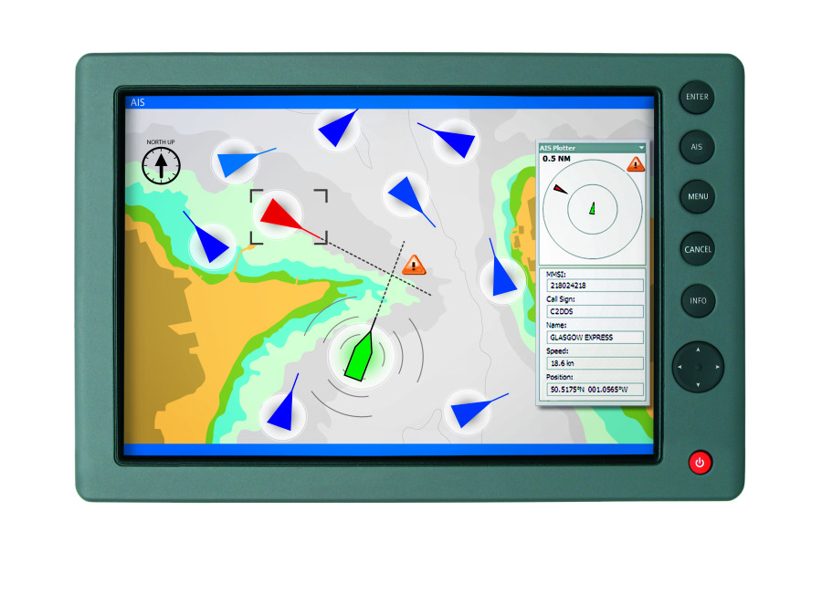
1 – Issue with a Chart Plotter/VHF Radio
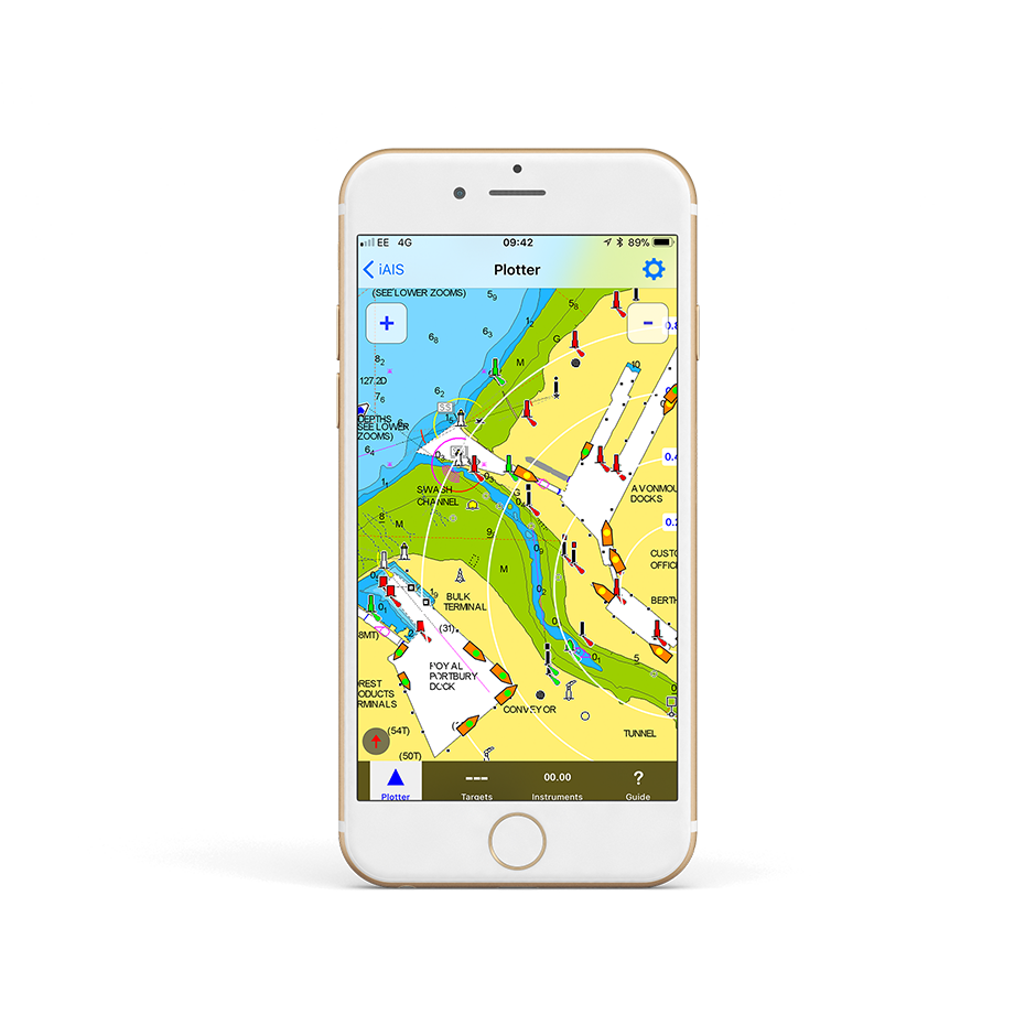
2 – Issue with a Navigation Software / App
I don’t have a good AIS range
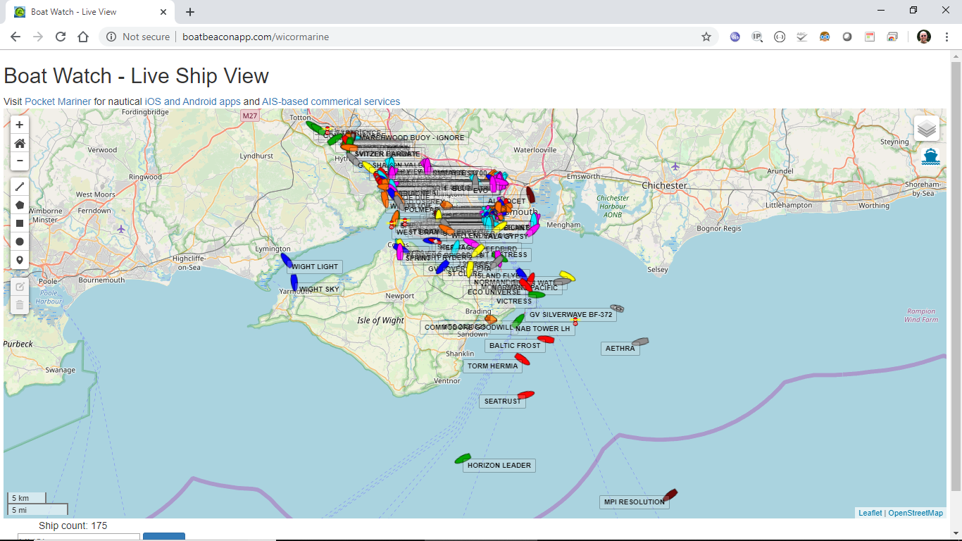
AIS Transmission/Reception depends on the AIS Class
If you don’t have a good range
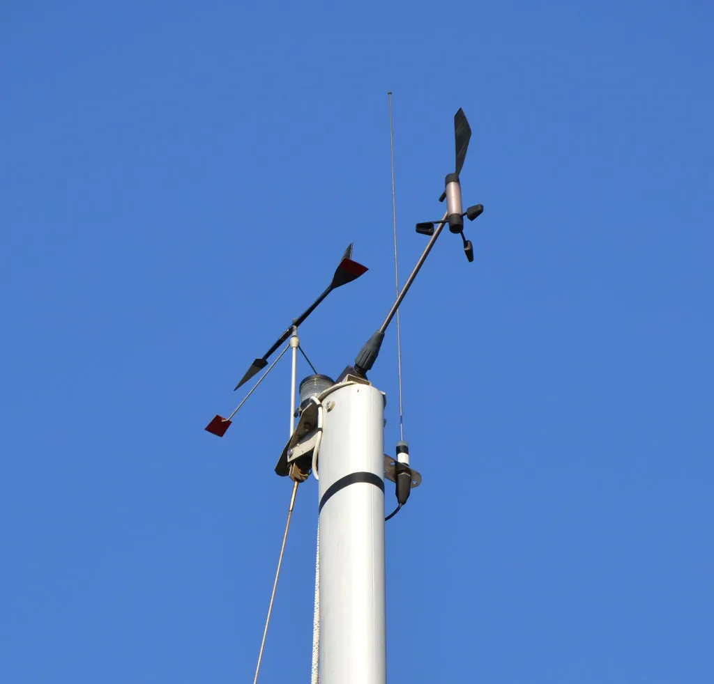
I don’t receive NMEA data on an iPad/iPhone app
How to manually reset an iAISTX?
Why my boat does not appear on MarineTraffic, VesselFinder, etc.?
ADDITIONAL NOTE
Which VHF antenna for an AIS?
AIS + VHF Antenna Separation

No GPS signal on an AIS Transponder due to loose FME connector
What’s the VSWR?
How to change the MMSI number?
What is the WiFi range/coverage of my product?
I have already a Wi-Fi router on board – can I join the product Wi-Fi to an existing network?
How to configure a navigation app or software?
How many devices can connect to the WiFi network?
What is the AIS transponder Wi-Fi network password?
How to configure an AIS transponder with the web interface?
1 – How to access the web interface
2 – Vessel details

3 – Vessel details

4 – AIS Status and Silent Mode
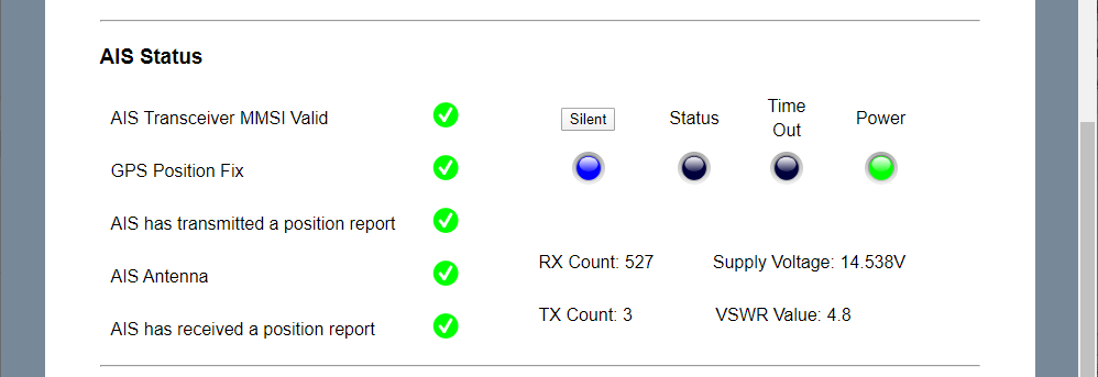
5 – View NMEA data and product firmware

AIT2500/AIT5000 – Disable NMEA 2000 GNSS PGNs

$PSMT,0,3,0x2C75B2FA,1,n2kognss 0,0*15
$PSMT,0,3,0x2C75B2FA,1,n2kognss -1,0*39
How to install the AIT5000?

