Technical FAQs
Before contacting us for support, please download and double check the latest issue of the product’s User Manual, which can be found here or search our extensive and growing list of frequently asked questions with helpful answers (see below).
Another support resource that may help you find solutions to your issue, is our searchable news blog here which has a wealth of information on apps, 3rd party product integration and product installation. Finally, if you prefer to watch rather than read, you can find videos on all of our products at our Youtube channel here.
AIS Transponders & Receivers
AIT1500, AIT1500N2K, AIT2000, AIT2500 & Nomad
Why can’t I program voyage destination?
Data such as: Destination Port, ETA, Navigation Status, Number of People on Board, etc. are only supported and transmitted by larger commercial vessels that are mandated to fit Class A AIS transponders. Class B and B+ transponders of the sort found on smaller vessels and pleasure boats, cannot transmit this data.
DSC and TX Warning Messages in proAIS2
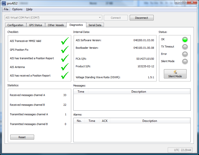
In the proAIS2 Diagnostics page, you will often see DSC and TX Attempt failed warnings displayed. These warnings are referring to normal AIS transponder behaviour and here is some more info on these messages…
The RX 1 / RX 2 DSC start / Stop message is a completely normal message, indicating when one of the AIS receivers has started/stopped a DSC channel management listening period. Class B equipment is required to listen to channel 70 periodically (at specific times defined in the standards) for DSC channel management commands. As Class B lacks the third receiver necessary to do this full time it is achieved by occasionally switching an AIS receiver to this channel.
TX attempt failed (Msg 18) and CP Busy messages are often seen, as Class B AIS is a ‘carrier sense’ system. It has to find a free slot to transmit in by listening just before transmission to check the slot is empty.When a transmission is scheduled a block of 10 potential slots is selected. It will attempt to transmit in the first of these slots.
If the slot is busy the ‘CP busy’ (meaning ‘candidate position busy’) message will be output. It will then try again in the next slot, and so on for the 10 slot block.
It is quite normal to see ‘CP busy’ messages in an area where other AIS vessels are operating. It simply means the first slot selected was busy. 99% of the time the transmission will be successful in one of the other 9 slots.
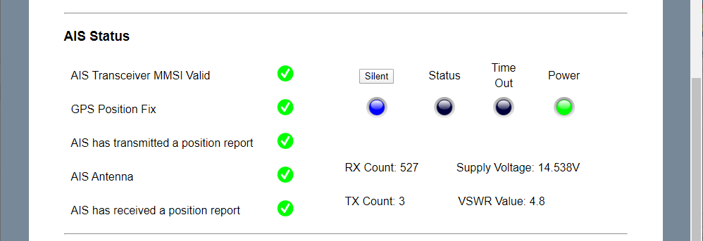
So long as the indicator remains green transmissions are occurring on schedule. If transmissions can’t be made because the AIS environment is simply too busy then the indicator will turn amber (this is incredibly rare – we have never witnessed it outside of test conditions).
In summary these messages are normal and can be ignored if the “Power” LED indicator is green.
NOTE – these conditions are not shown as an error or alarm in proAIS2 , just in the ‘messages’ box. Anything in the ‘messages’ box is just for info and not a fault or alarm; those are shown in the ‘Alarms’ box.
Errors on proAIS Diagnostics Table
If you see anything in the Messages section of the proAIS2 Diagnostics page, then these are just temporary warnings and usually nothing to worry about, it is when critical events happen that you need to worry and these appear in the Alarms section and invariably also cause a change in LED status and one or more green ticks changing to red crosses.
The two most common messages you will see are….
1) RX 1 / RX 2 DSC start / Stop message
This message indicates when one of the AIS receivers has started/stopped a DSC channel management listening period. Class B equipment is required to listen to channel 70 periodically (at specific times defined in the standards) for DSC channel management commands. As Class B lacks the third receiver necessary to do this full time it is achieved by occasionally switching an AIS receiver to this channel.
2) TX attempt failed (Msg 18) and CP Busy messages
Class B AIS is a ‘carrier sense’ system. It has to find a free slot to transmit in by listening just before transmission to check the slot is empty.
When a transmission is scheduled a block of 10 potential slots is selected. It will attempt to transmit in the first of these slots.
If the slot is busy the ‘CP busy’ (meaning ‘candidate position busy’) message will be output. It will then try again in the next slot, and so on for the 10 slot block.
It is quite normal to see ‘CP busy’ messages in an area where other AIS vessels are operating. It simply means the first slot selected was busy. 99% of the time the transmission will be successful in one of the other 9 slots.
So long as the indicator remains green transmissions are occurring on schedule. If transmissions can’t be made because the AIS environment is simply too busy then the indicator will turn amber (this is incredibly rare – and is yet to be witnessed outside of test conditions).
In summary these messages are normal and can be ignored if the indicator is green
NB – it’s not shown as an error or alarm in proAIS2 , just in the ‘messages’ box. Anything in the ‘messages’ box is just for info and not a fault or alarm; those are shown in the ‘Alarms’ box.
What’s the LEN value of the AIS?
All Digital Yacht AIS transponders have the LEN value = 1, except our AIT1500N2K which has LEN = 6.
AIT2500/AIT5000 – Disable NMEA 2000 Heading Reception
All Class B and Class B+ AIS transponders can transmit the True Heading of the vessel as part of the dynamic data they transmit to other vessels; MMSI Number, Position, COG, SOG, etc. If received most charting systems will plot the AIS target with both the COG and True Heading vector displayed, useful when the vessel is stationary and COG becomes unstable/inaccurate.
Our AIT2500 and AIT5000 units can receive the True Heading (HDT or THS sentences) data via their Low Speed NMEA 0183 Input (Yellow+ and Green- wires) or via PGN#127250 Vessel Heading on NMEA 2000.
However, not all NMEA 2000 systems will transmit True Heading and in some cases they transmit a wrong value or just a fixed 000º. This results in the AIS target being plotted with a very strange heading vector or the boat appearing to be moving side-ways or backwards.
If this happens and you cannot correct or suppress the True Heading value on the NMEA 2000 network, then you can stop the AIT2500/AIT5000 from receiving True Heading over NMEA 2000, by following the procedure below….
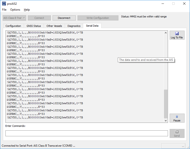
Using the proAIS2 software, go to the Serial Data tab and then copy and paste the following commands in to the box at the bottom of the page and click the “Send” button (see image below).
- To stop reception of True Heading data over NMEA 2000 send this command:
$PSMT,0,3,0x2C75B2FA,1,n2kignss 0,0*13 - To enable it again send this command:
$PSMT,0,3,0x2C75B2FA,1,n2kignss 1,0*12
….if the command was successfully received and actioned, you should see Transponder respond with…
- $PSMT,255……….etc. (basically, the same as the command but 255 instead of 0 after the $PSMT, text)
Red Status LED flashing on my AIS transponder
A flashing RED Status LED indicates a high VSWR reading or potentially a Power Amplifier fault.
For the flashing RED Status LED issue, with the 12v power turned off to the AIS Transponder, I would visually inspect the BNC antenna connector on the AIS and make sure there are no signs of connector damage. Then connect up whichever VHF antenna you have the most confidence in. Now power ON the AIS Transponder and immediately join its wireless network and bring up the web interface before the unit has got a GPS position fix and tried to transmit or use ProAIS2 if your AIS transponder don’t have a web interface.
Now watch the VSWR reading and see what value is displayed after the first couple of transmissions. If it is greater than 5:1, then it has a high VSWR and will soon start to flash the RED Status LED.
The most common cause is the VHF antenna and connections, but if you are confident that they are all fine, then it must be the unit itself and we will need to get it back for warranty repair.
My AIS Transponder is not transmitting
If you think that your AIS transponder is not transmitting your position then this procedure might help you. The first step is to check if your AIS transponder is actually transmitting. If you are then sure that your AIS transponder is not transmitting then the next part explains you the factors to check.
1 – Check if your AIS is transmitting or not
With ProAIS2 or iAISTX/AIT5000 Web Interface
Using the proAIS2 configuration software or the iAISTX/AIT5000 web interface allows you to see if the GPS position is OK. You can monitor the AIS reception of other vessels. As well as ensure that there are no errors or alarms. However, if you are new to AIS, there is always that nagging doubt as to whether other vessels are seeing you.
Check with a local AIS Receiver/Transponder
The best test of a Class B transponder is to ask someone else in your marina, who has AIS, to check that they are receiving you on their system. If your vessel is stationary, then a transponder will only transmit every 3 minutes. This increases to every 30 seconds when your speed over the ground (SOG) is greater than 2 knots. Therefore, do allow some time for them to detect you. Also when they first receive your transmission, the only data they will see is your position, speed, course and MMSI number. It can take up to 6 minutes to receive your “Static Data” (boat name, call sign, vessel type, dimensions, etc.). This is normal and is the way the AIS system regulates the amount of data being transmitted.
Check with MarineTraffic, Vessel Finders, etc.
The other increasingly common method of testing an AIS transponder is to look on one of the online “live” AIS websites and the most popular of the free services is MarineTraffic.com
However, it is important for you to be aware of the limitations of these online sites. As a result, do not assume that you will always be picked up by them. Each of the different online services are only as good as their network of AIS receiving stations. In many cases enthusiasts/volunteers operate these. In some areas the coverage is great but there are definitely “holes” in coverage.
2 – Find out the reasons why your AIS is not transmitting
If you are now sure that your AIS transponder is not transmitting then you should follow the following steps.
You must use ProAIS2 for your AIT1500, AIT2000, AIT2500, AIT3000 or Nomad. However, for the iAISTX, iAISTX Plus or AIT5000, you must use the built-in web interface.
With proAIS2’s diagnostics tab or the iAISTX/AIT5000 web interface, you can check if an AIS transponder has an issue or not.
A- Check if your AIS receives a good GPS position.
Without a good GPS fix, an AIS transponder cannot transmit correctly your position. By going to the GPS Status tab in ProAIS2, you can see the GPS reception. If you have one of our AIS transponder with built-in GPS antenna, then you should consider installing a GPS booster (for more information, click here).
If you have an external GPS antenna then make sure that the connectors are correctly tight and also that the antenna is outside and has a clear view over the sky.
B- Check the VHF antenna
In the Diagnostics Tab in ProAIS2 or within the iAISTX/AIT5000 web interface, you can see the VSWR ratio. The VSWR ratio is explained in the FAQs. If your VSWR ratio is above 3, then you must check the VHF antenna connectors and the cable.
If possible, use another VHF aerial to check if the AIS transmits better.
C – Check that all the data have been entered
In the Configuration Tab in ProAIS2, you must make sure that all the boat details have been added (MMSI, VHF Call Sign, Name, Dimensions, etc.)
You can send us via email a screenshot of the ProAIS2 diagnostics tab or your iAISTX/AIT5000 web interface, we will then let you know whether the product works well or not.
This video might also help you out:
I cannot display AIS targets
If you encounter an issue with AIS showing on your display (navigation software or chart Plotter) then you should follow this procedure.
1 – Issue with a Chart Plotter/VHF Radio
If you cannot display AIS targets on your Chart Plotter or VHF radio, then follow this:
- If you have connected your AIS to your Chart Plotter/VHF Radio via NMEA 0183 wires, then you must make sure that you have used the NMEA 0183 38400 baud wires (Orange + & Brown – for Digital Yacht AIS Transponders). The second step is to check your Chart Plotter / VHF Radio settings. The best solution here is to check your product manual but you must make sure that the NMEA 0183 port is set at 38400 baud and also that AIS targets are activated.
- If you have connected your AIS to your Chart Plotter/VHF Radio via NMEA 2000, then you must make sure that the NMEA 2000 network is working properly. This page might answer to your question. You should also make sure that AIS targets are activated in your chart plotter / VHF radio settings.
2 – Issue with a Navigation Software / App
If you cannot display AIS targets on your navigation software or app then follow this:
- For an Android/iOS app: The first step is to make sure that all apps are closed in the background, then you are connected to the product WiFi network. The second step is to configure your navigation app. This is explained in this page.
- For a PC Navigation Software: The first step is to make sure that the USB drivers are installed. You can download them here if needed. You must then find out the port COM allocated to your USB port. The last step is to configure your navigation software. This is explained in this page.
I don’t have a good AIS range
AIS Transmission/Reception depends on the AIS Class
- A Class B AIS transponder transmit at 2 watts whereas a Class A Transponder at 12.5 watts. The Class B+ SOTDMA transponder transmits at 5 watts. This difference in power has a huge impact on the transmission range of each transponder.
- For a Class B AIS transponder, the transmission range is usually 5 to 7 miles in perfect conditions. This means using a good VHF antenna, placed as high as possible and clear of other antennas. The cables and connectors must also be in good conditions. For a Class B+ 5W SOTDMA, it typically transmits at up to 15 miles.
- However, for the AIS reception, a Class B/Class B+ transponders can receive Class A AIS at up to 30 miles.
If you don’t have a good range
- If you are using a VHF antenna splitter for your transponder, make sure it is a ZeroLoss VHF Splitter like our SPL1500, SPL2000. You must also check the connectors and the cables between the VHF splitter and the AIS.
- If you are using a dedicated VHF antenna for your transponder, then make sure that it is at least 2 meters away from other VHF antennas. Also, you must check the VHF antenna, its cable and connectors.
If you don’t have a good range, we suggest you testing with another VHF aerial to check if you have a better range.
I cannot connect the USB of my AIS transponder
If you are unable to connect your AIS transponder USB, then you should follow this section. The USB drivers are automatically downloaded with ProAIS2.
I am sure your USB drivers and proAIS2 software are fine, the key issue is the power up sequence. Please power cycle the transponder in the following manner, which works every time when you have it connected to a PC….
- Turn off the 12/24v supply to the transponder and unplug the USB cable
- Close the proAIS2 software and any other navigation software that uses COM Ports or USB Virtual COM ports
- Plug in the USB cable – the Red and Yellow LEDs should illuminate on the transponder
- Run the proAIS2 software, make sure the AIS Transponder is shown in the drop down menu and click the “Connect” Button.
- The PC should query the transponder and after a second or two, display the boat data (MMSI number, Name. etc.) in the data boxes
- Turn on the 12/24v supply to the transponder and it will start to try and get a position fix and then start transmitting
How to configure an AIS with ProAIS2 or AISConfig?
This article explains how to configure an AIS transponder, either using our proAIS2 software for PC/MAC or with a free Android app called AISConfig. This article is for AIT1500, AIT1500N2K, AIT2000, AIT2500, AIT3000 and Nomad.
1- proAIS2 (available on PC & Mac)
The proAIS2 software is included on the CD-ROM-rom supplied with all of our AIS transponders. If you do not have the CD-ROM or your laptop cannot read a CD-ROM, then you can download the software for Windows or for Mac by clicking here. The functionality of the proAIS2 software is the same on Windows or Mac.
Installation of the proAIS2 software, also installs the USB drivers and we recommend not plugging the transponders USB cable in to the PC/Mac until after you have installed proAIS2. Once the installation is complete, plug the USB cable in to the computer to complete the USB driver installation.
The transponder receives enough power from the USB connection to power the processor and ancillory circuitry required to configure the transponder, however the GPS will not get a fix, the NMEA interfaces will not be working and the transponder will not transmit while on USB power.
For more information on installing proAIS2 on a Mac, please refer to a previous article by clicking here.
Digital Yacht are not the only company that supply proAIS2 with transponders, but to our knowledge, we are the only company to produce a video showing how to configure and diagnose Class B transponders with it. So we hope that not only Digital Yacht users but owners of other brands will benefit from this video. To find out how to use the proAIS2 software to configure an AIS transponder, please
2- AISConfig (available on Google Play Store)
The AISConfig app is a free application that can be downloaded from the Google Play Store. You can download it by clicking here. The AIS transponder must have a built-in WiFi interface (such as Nomad, AIT3000, etc.) or must have a NMEA WiFi server to be configured with the app.
Initial programming of the unit with your boat’s MMSI, vessel details, etc. plus monitoring of the LEDs, key performance criteria and switching Silent mode ON/OFF can all be done from the App.
To find out how to use the AISConfig app to configure an AIS transponder, please watch the video below:
Why my boat does not appear on MarineTraffic, VesselFinder, etc.?
- It is important for you to be aware of the limitations of these online sites. As a result, do not assume that you will always be picked up by them. Each of the different online services are only as good as their network of AIS receiving stations. In many cases, these shore stations are operated by AIS enthusiasts/volunteers who have a home/office by the sea. In many areas the coverage is great but there are definitely “holes” in coverage.
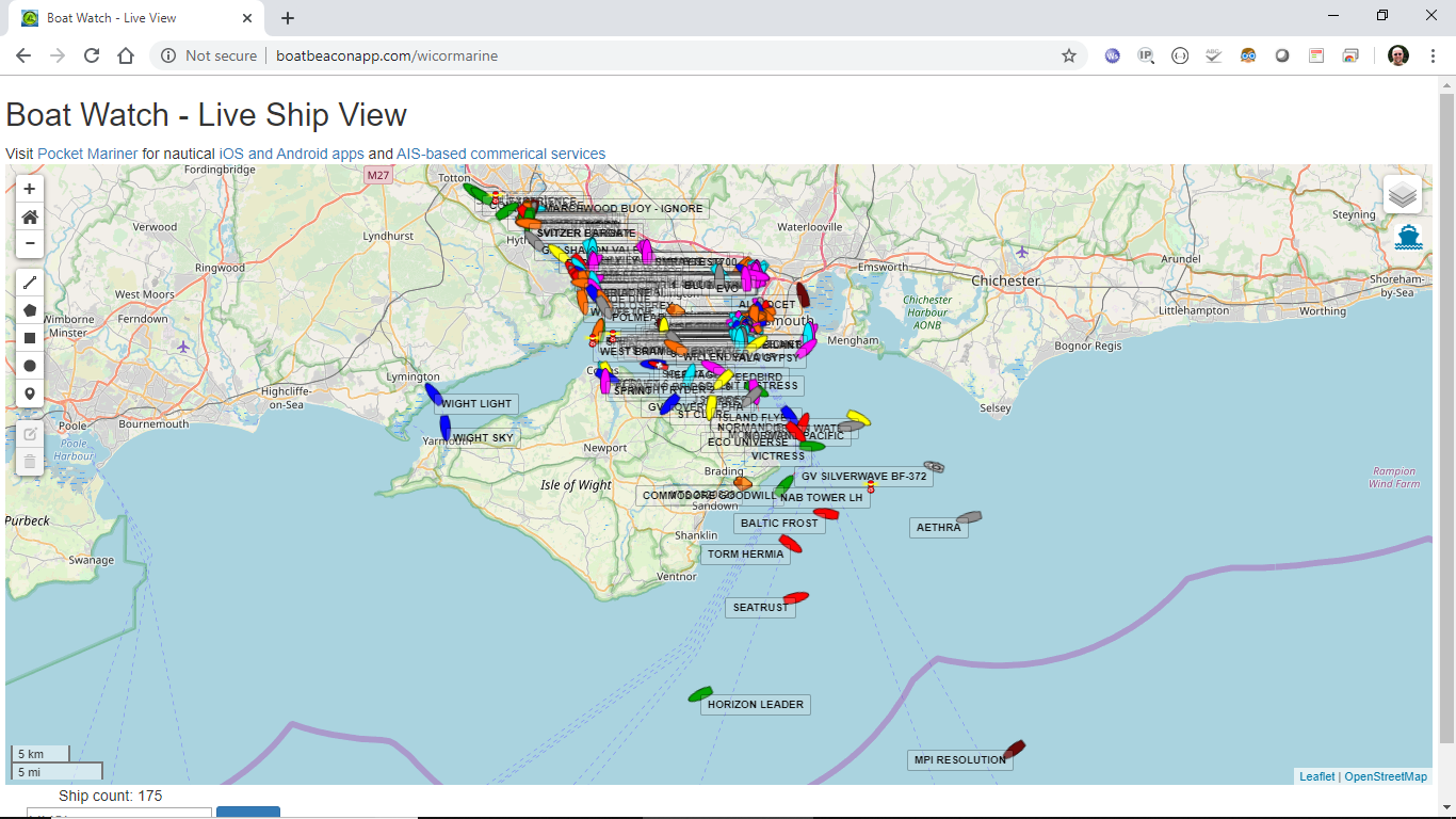
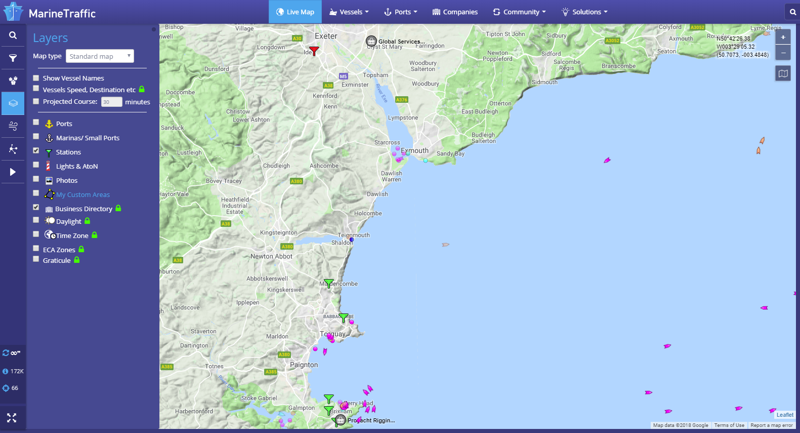
- One of the good features of the Marine Traffic service, is that you can display the locations of the receiving stations and see if they are currently online or offline. From the Marine Traffic home page, zoom in to your location on the map. Then on the left hand side of the screen, click on the “Layers” icon. This will show a series of tick boxes to display different layers of data will appear. Click the “Stations” tick box and you will see a series of Antenna type icons on the map; green if they are online (receiving data), red if they are offline and orange if they are online but giving poor reception performance.
- In the image below, you can see the the UK port of Exmouth. If you were testing your Class B transponder here today, then you would think you were not transmitting. Just one receiving station being offline can create a big hole in coverage and the next receiving station going East is Bridport around 35 miles away. This is a popular section of water and yet you can only see a few vessels between Torquay and Lyme Regis.
- A Class B transponder transmits at 2 Watts (about a third of the power of a hand held VHF). Therefore even in perfect line of sight conditions, the best range you can expect is about 8NM. It is important to check if there is a receiving station within 5-8NM of your location and if there are any other Class B vessels displayed near you.
- If you are more than 5-8NM from the receiving station or there is not a good clear line of sight between the station and your location, then your transmission is unlikely to be received.
- You should note that Commercial vessels and some larger pleasure craft have Class A Transponders. These transmit at 12.5 Watts and have a much greater transmit range 20-25NM. As a result, these vessels may be displayed near your location, even if your Class B transmission is not received.
- Finally, it can take an hour or so for a new AIS (MMSI number) to be recognised and stored in the database of these online services. Consequently, if you are confident that you are in range of an online receiving station, leave your transponder on for a few hours. This will give the online service time to detect and record you in their database.
ADDITIONAL NOTE
Another nice feature of Marine Traffic, is that you can drill down in to the details of a particular receiving station. Click on the icon of the Station of interest and a summary of the receiving Station’s information will be displayed. By clicking the Green “Details and Statistics” button, you can get a wealth of information about the station, its statistics and “live” AIS target reception list.
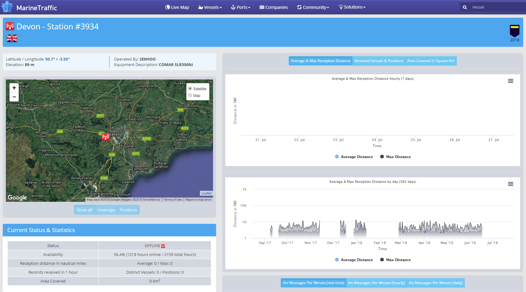
- As you can see, this particular station in Exmouth is regularly offline for quite long periods. Even when it is online, it has a rather poor 10NM reception range.
- For anyone that lives or has a business close to the sea and who would like to be part of an online AIS network, please contact us about our AISNet product, which can connect to your home/office network and put your local AIS reception data online.
Which VHF antenna for an AIS?
One of the most common questions we are asked by our AIS customers, is “what antenna should I use for my AIS ?”, so we thought we would post a short article to provide an answer on VHF Antenna Options for AIS.
Basically there are two VHF antenna options for AIS; fit a second dedicated VHF antenna a suitable distance from the vessels main VHF antenna. Or alternatively, use the main antenna for both VHF and AIS by fitting a special device called a “Splitter”.
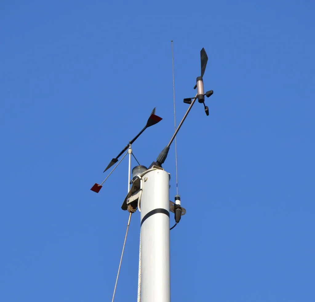
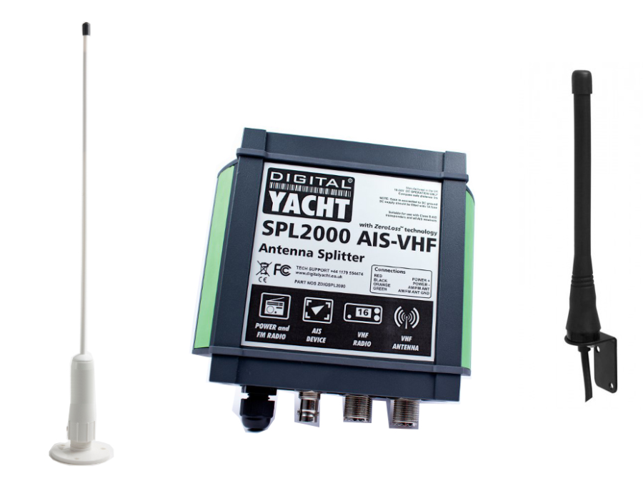
Generally our recommendation for yacht owners who want to fit an AIS, is to use a “Zero Loss” splitter like our SPL2000. By utilising the main VHF antenna at the top of the mast, you will definitely get maximum transmit range. Plus the ease of installation often makes it a cheaper option than paying for a second antenna to be installed.
However, for power boaters who do not benefit from the height advantage of using the main antenna at the top of the mast. As well as for AIS receiver owners where the splitter can often cost more than the AIS receiver itself. It is often desirable to fit a second VHF antenna. This is particularly apparent if you intend to save money by doing the antenna installation yourself.
AIS operates on two dedicated channels within the marine VHF frequency range – 156.0 to 162.025 MHz. The two AIS channels are at the top end of this range namely; 161.975 and 162.025 MHz (channels 87B and 88B). Most VHF antennas are designed to give maximum gain across the whole VHF frequency range centred on Channel 16 (156.8 MHz).
Pretty much all of the antenna manufacturers now produce “AIS Tuned” antennas. These have their centre frequency shifted from Channel 16 to 162Mhz (exactly half way between the two AIS frequencies). If you choose to mount your AIS antenna on the stern rail of a yacht or radar arch of a power boat. Then using an “AIS tuned” antenna is a good idea. This will allow you to get an extra bit of gain. Thus compensating for the antenna being effectively at deck level.
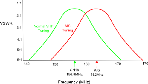
The graph above shows how the tuning of the antenna to 162MHz gives it an extra boost in VSWR (gain) across the two AIS frequencies.
Which ever option you choose, having AIS on your boat will without doubt make your sailing experiences safer. As well as less stressful in poor visibility or when crossing busy shipping lanes. Even a simple receiver with a small whip antenna at deck level is effective. Allowing you to keep informed of what ships are around and which ones you need to keep an eye on.
AIS + VHF Antenna Separation
The AIS system works on two channels in the VHF frequency range and in order to receive or transmit AIS information it is necessary for the AIS unit to be connected to a VHF antenna. One option is to fit a VHF splitter such as our SPL2000, which allows both the VHF radio and the AIS to use the boat’s main VHF antenna. The other option is to fit a second VHF antenna which is then just connected to the AIS.
Any VHF antenna can be used, although some antennas are “AIS tuned” to get maximum gain on the two AIS channels and also have a BNC type connector fitted (common on AIS units), rather than the traditional PL259 VHF connector.
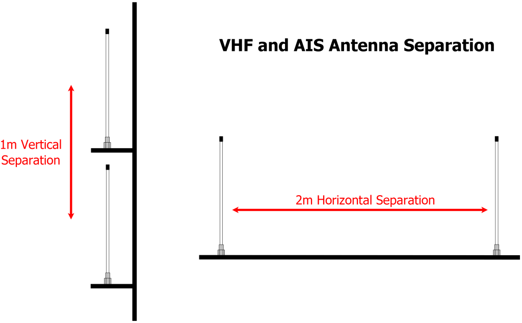
If you decide to fit an additional VHF antenna for the AIS, you want to mount it as high as possible but you should be aware that it cannot be mounted right next to the existing VHF antenna and a certain amount of separation must be maintained to avoid the 25 watts of transmit power from your VHF radio going straight in to the AIS receiver circuitry, potentially damaging it. The diagram below shows the recommended minimum separation of the antennas.
No GPS signal on an AIS Transponder due to loose FME connector
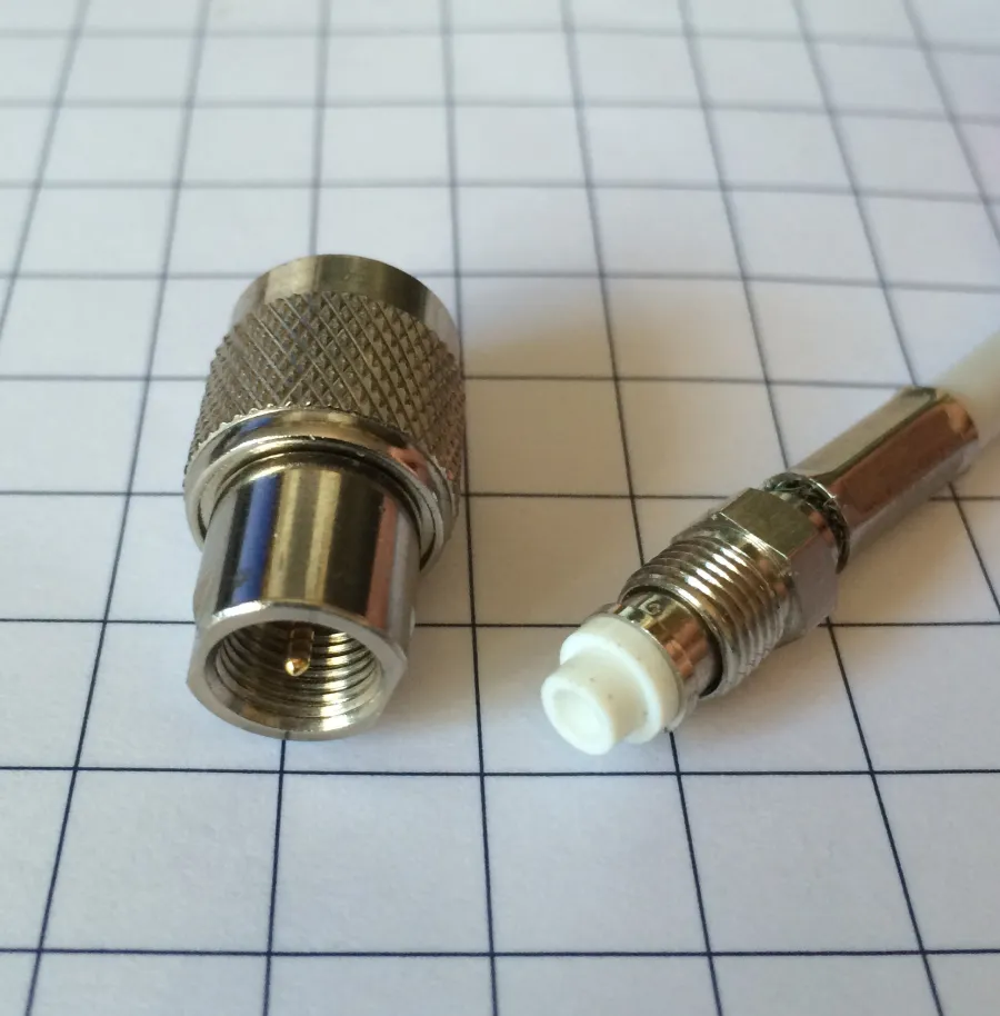
Our AIS transponders are supplied with a GPS antenna that has a 10m cable terminated in an FME connector (right hand connector in the above image).
These connectors are very slim, not much larger than the coax cable and are much easier to route through the boat. We also supply an FME to TNC adaptor for connecting the cable to the transponder (left hand connector in the above image).
Today we were reminded of the importance of ensuring this adaptor is firmly screwed on to the cable, when a US customer reported that their AIT2000 had stopped getting a GPS fix. After using the proAIS2 software to confirm that the GPS signals were very low, we asked the customer to check the GPS antenna connections to the AIT2000 and sure enough found that the FME connector had become loose and was no longer making a good connection.
A quick tighten of the FME connector in to the adaptor and the AIT2000 started to get a GPS fix again and the customer could continue their cruise.
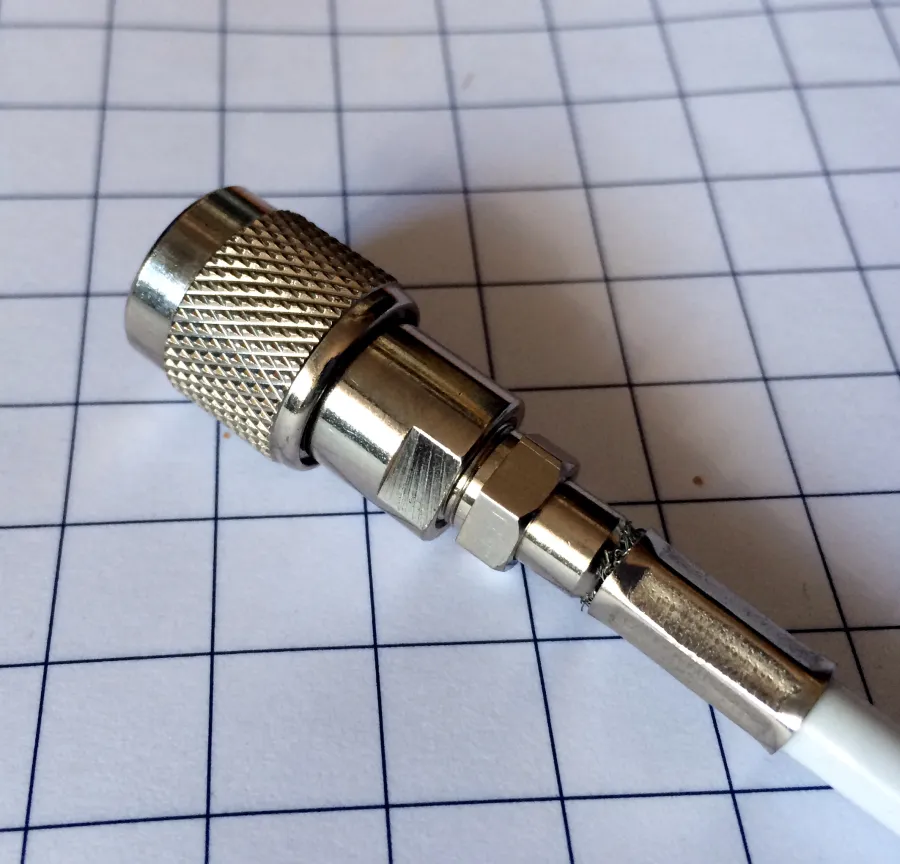
The nut on the FME connector is 8mm (AF) and the TNC adaptor has two flat indents that are 9.5mm (AF). You can tighten the two connectors quite tightly but avoid using too much force which could damage the connector and cause a different set of problems. The image below shows the FME fully tightened in to the adaptor and there should be about a 1.5mm gap between the FME nut and the collar of the adaptor when properly tightened.
Our GV30 combo GPS and VHF antenna also uses FME connectors and is supplied with a TNC and BNC adaptor, which should also be tightened in the same way.
What’s the VSWR?
Checking the VHF/AIS Antenna, is the most difficult test. As a result, it is the one that we get the most technical support calls about. Therefore, we thought a blog post on the subject would help.
It is surprisingly common for yacht owners to install an AIS transponder with an antenna splitter and then find that their “old faithful” VHF antenna at the top of the mast is actually not as good as they thought it was. The reason for this, is that the top of the mast is a pretty hostile place. Over time, the antenna will suffer high levels of salt water and UV exposure, coupled with large temperature swings, vibration, G forces, etc. All of which start to degrade the materials and cabling. Alongside the occasional stepping of the mast, with possibly a through-deck connection or cable join inside the hull. You can see that there are lots of possibilities for the antenna to not be in tip-top condition.
All AIS transponders perform a continuous series of self tests, including a VHF antenna test. This is often the first time, in many years, that the VHF antenna at the top of the mast has been tested. Therefore, it is not unusual for some to fail the test. The reality is, that a VHF radio or AIS will happily get some level of reception even if you just connect a wire to it. As a result, you can appear to be receiving AIS data but your transmission is poor. This is due to an old/degraded VHF antenna that has a high Voltage Standing Wave Ratio (VSWR).
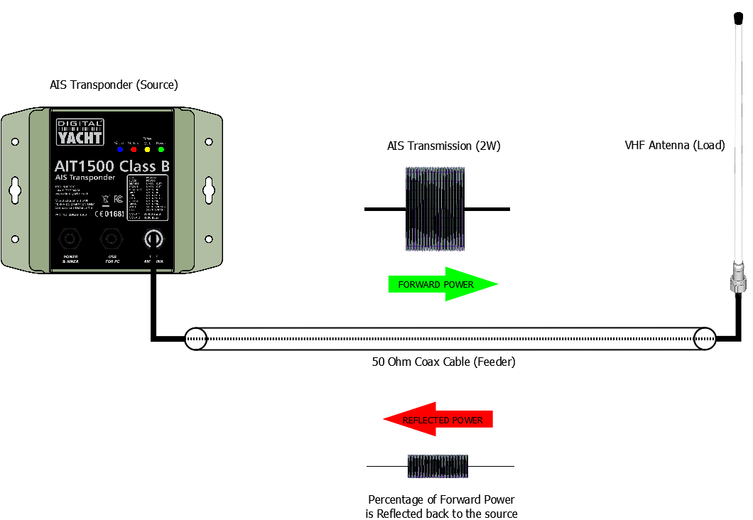
The VSWR of an AIS transponder, is a measure of the level of standing waves present in the antenna cable (feeder). Standing waves are the signals/power that do not radiate in to the air, by the antenna (load), but reflect back down the cable to the transponder (source). In an ideal world, all of the power sent to the antenna would transmit through the air to other vessels. However, this only happens if the impedance (AC resistance) of the source, feeder and load are identical (50 ohms).
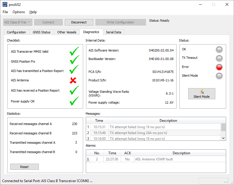
This perfect matching of the impedances would result in a VSWR of 1:1. Although in “real life” pleasure boat installations, it is more likely to be between 1.1:1 and 2.5:1. In the diagnostic page of our proAIS2 software, the you can see the VSWR and will update upon every transponder transmission. By keeping an eye on the Transmit Counter you can see when a transmission takes place. You will probably see a slight change (in the decimals) each time the VSWR is measured, which is normal. If you see a bigger fluctuation, this is indicative of a poor connection or water ingress in the antenna cable/connections.
If the measured VSWR goes above 5:1, the RED Status LED will illuminate and a VSWR alarm displayed in proAIS2 (see top image).
Understanding the importance of having a good VHF antenna, with a low VSWR to get the best possible AIS transponder performance (transmit range) is key. We hope this article helps our customers have a better appreciation of this technology.
How to change the MMSI number?
Once entered and confirmed, the MMSI number on an AIS can only be changed by a technical dealer or by Digital Yacht. This is a government requirement in many countries to ensure the security of the AIS system.
If you need your MMSI number reset or changed, we offer a reprogramming service.
The cost for this is £65.00/75.00€ + Return Shipping (+VAT – if applicable)
If you would like to go ahead with this, please complete and print the following:
- AIS PROGRAMMING – for MMSI details.
- SERVICE RETURN FORM – for return shipping details.
If you do not have Microsoft Word or a means of editing Word documents, please print and complete this PDF version.
Please return the AIS transponder with the printed AIS PROGRAMMING form to the following address:
- USA/UK/ROW: Digital Yacht Service, 7 Farleigh Court, BS48 1UR, Flax Bourton, United Kingdom
- Europe/EU: Digital Yacht, 12 Boulevard des Belges, 76000 Rouen, FRANCE
If you’re returning a product from outside the EU, please put a value of GBP £10.00/ USD $14.00 / EUR €12.00 for the product and if requested by the freight company or postal service, use MARINE ELECTRONIC EQUIPMENT as a description and the commodity code 90148000.
The reason for return can be Product Service or Return for Repair.
Alternatively, the MMSI can be reset by any local NMEA certified/technical marine dealer who will have the cables, programming leads and software to complete.
For Nomad and Nomad2 customers, please contact us via our ticketing system.
AIT5000, iAISTX, iAISTX Plus & Nomad 2
DSC and TX Warning Messages in proAIS2
In the proAIS2 Diagnostics page, you will often see DSC and TX Attempt failed warnings displayed. These warnings are referring to normal AIS transponder behaviour and here is some more info on these messages…
The RX 1 / RX 2 DSC start / Stop message is a completely normal message, indicating when one of the AIS receivers has started/stopped a DSC channel management listening period. Class B equipment is required to listen to channel 70 periodically (at specific times defined in the standards) for DSC channel management commands. As Class B lacks the third receiver necessary to do this full time it is achieved by occasionally switching an AIS receiver to this channel.
TX attempt failed (Msg 18) and CP Busy messages are often seen, as Class B AIS is a ‘carrier sense’ system. It has to find a free slot to transmit in by listening just before transmission to check the slot is empty.When a transmission is scheduled a block of 10 potential slots is selected. It will attempt to transmit in the first of these slots.
If the slot is busy the ‘CP busy’ (meaning ‘candidate position busy’) message will be output. It will then try again in the next slot, and so on for the 10 slot block.
It is quite normal to see ‘CP busy’ messages in an area where other AIS vessels are operating. It simply means the first slot selected was busy. 99% of the time the transmission will be successful in one of the other 9 slots.
So long as the indicator remains green transmissions are occurring on schedule. If transmissions can’t be made because the AIS environment is simply too busy then the indicator will turn amber (this is incredibly rare – we have never witnessed it outside of test conditions).
In summary these messages are normal and can be ignored if the “Power” LED indicator is green.
NOTE – these conditions are not shown as an error or alarm in proAIS2 , just in the ‘messages’ box. Anything in the ‘messages’ box is just for info and not a fault or alarm; those are shown in the ‘Alarms’ box.
AIT5000 Voltage Problem
A couple users have seen that the Supply Voltage on the Status Page is showing as around 8v but when they disconnect and test are getting 12v +.
The Green Power LED is a very good indicator that the AIT5000 transponder is working correctly. The Status web page shows the default values and indicates that there is no NMEA communication between the transponder and the web browser.
The most common causes of this are:-
- That the baud rate of NMEA 1 is not set to 38400 baud – this can be checked by using the proAIS2 software running on a laptop and connecting the AIT5000 via USB.
- That the NMEA 0183 Output wires (Orange and Brown) on the main Power/Data cable, are shorted together or to other wires, stopping the NMEA 0183 data transmission.
Please check that neither of these two issues are causing your problem. If you are still experiencing an issue, please contact our Support Team by creating a ticket here.
Why does my iPhone/iPad show “Weak Security” or no WiFi icon?
The WiFi icon on the iPhone not showing is the wireless network you are connected to, does not have an internet connection. This is a fairly recent change. On earlier versions of iOS this icon was always displayed and shows a user if they are using WiFi or 4G connection for internet, which is an important thing to know.
Most users will be connected to normal home or office wireless networks that have an internet connection. Only a small percentage of iPhone users will have an iAISTX or similar wireless device that does not have internet connection, so having a feature for the majority won the day.
The weak security message is also a recent change, as Apple are pushing all of their users to move to the latest and most secure WPA3 security. The reality is that WPA2 is still very secure and still used on the majority of wireless networks, so it is nothing to be worried about. Even if a hacker did manage to crack your iAISTX, all they would gain is the location of all the AIS equipped vessels around you – not any sensitive banking or personal info.
Can I use an external GPS antenna for my AIS Transponder, or do I have to use the supplied antenna?
In the original International Product Specification for Class B AIS Transponders, it was dictated that they should be “stand alone” systems that did not require any input from other devices. For this reason, you will not find any AIS Class B transponders that can take their position input from an external NMEA 0183 or NMEA 2000 GPS sensor.
I am afraid that you will need to use the supplied GPS antenna with your iAISTX, but if your boat has a GRP hull, then you might be able to install the GPS antenna inside the hull and not go to all the trouble of routing it externally. Just find a suitable location and use the GPS signal strength display on the iAISTX’s web interface to check that you are getting good reception, before finally bolting it down.
AIT2500/AIT5000 – Disable NMEA 2000 Heading Reception
All Class B and Class B+ AIS transponders can transmit the True Heading of the vessel as part of the dynamic data they transmit to other vessels; MMSI Number, Position, COG, SOG, etc. If received most charting systems will plot the AIS target with both the COG and True Heading vector displayed, useful when the vessel is stationary and COG becomes unstable/inaccurate.
Our AIT2500 and AIT5000 units can receive the True Heading (HDT or THS sentences) data via their Low Speed NMEA 0183 Input (Yellow+ and Green- wires) or via PGN#127250 Vessel Heading on NMEA 2000.
However, not all NMEA 2000 systems will transmit True Heading and in some cases they transmit a wrong value or just a fixed 000º. This results in the AIS target being plotted with a very strange heading vector or the boat appearing to be moving side-ways or backwards.
If this happens and you cannot correct or suppress the True Heading value on the NMEA 2000 network, then you can stop the AIT2500/AIT5000 from receiving True Heading over NMEA 2000, by following the procedure below….
Using the proAIS2 software, go to the Serial Data tab and then copy and paste the following commands in to the box at the bottom of the page and click the “Send” button (see image below).
- To stop reception of True Heading data over NMEA 2000 send this command:
$PSMT,0,3,0x2C75B2FA,1,n2kignss 0,0*13 - To enable it again send this command:
$PSMT,0,3,0x2C75B2FA,1,n2kignss 1,0*12
….if the command was successfully received and actioned, you should see Transponder respond with…
- $PSMT,255……….etc. (basically, the same as the command but 255 instead of 0 after the $PSMT, text)
Red Status LED flashing on my AIS transponder
A flashing RED Status LED indicates a high VSWR reading or potentially a Power Amplifier fault.
For the flashing RED Status LED issue, with the 12v power turned off to the AIS Transponder, I would visually inspect the BNC antenna connector on the AIS and make sure there are no signs of connector damage. Then connect up whichever VHF antenna you have the most confidence in. Now power ON the AIS Transponder and immediately join its wireless network and bring up the web interface before the unit has got a GPS position fix and tried to transmit or use ProAIS2 if your AIS transponder don’t have a web interface.
Now watch the VSWR reading and see what value is displayed after the first couple of transmissions. If it is greater than 5:1, then it has a high VSWR and will soon start to flash the RED Status LED.
The most common cause is the VHF antenna and connections, but if you are confident that they are all fine, then it must be the unit itself and we will need to get it back for warranty repair.
AIS is not displaying boats’ names
When we get reports like this, it invariably turns out to be Chart Plotter or Application that has a problem – usually software related.
The reason for this, is that AIS units do not differentiate between different types of AIS messages; either the regular dynamic ones that include the MMSI number and the position/course/speed of the vessel or the more infrequently transmitted static ones that include the MMSI number, name, dimensions, boat type, etc. and in the case of Class A vessels the voyage data that includes navigation state, destination, ETA, etc.
An AIS unit either receives all of the messages or none. In theory, if the AIS was getting poor reception and missing some messages then because a boat might send 10 dynamic messages for every 1 static message, you are more likely to see the boat without the static data, but it would be random and some boats would have their names. The application only needs to receive the static data once for a target, and then it is in its temporary AIS database for the duration that the application is running.
As I mentioned, the Chart Plotter or Application maintains its own AIS database where it ties together the MMSI numbers in the dynamic and static messages and builds up an AIS target list where every boat should (within 6 minutes) have a name, dimensions, boat type, etc.
The static messages are longer than the dynamic ones and might be split across a couple of UDP network packets. You could try setting the iAISTX to operate in TCP mode and then setup a new Device on the Navionics App; TCP mode, Host = 192.168.1.1 and Port = 2000.
TCP mode is a guaranteed delivery protocol with error checking, packet sorting and re-transmit functionality, that ensures all network packets are always fully received. The downside, is that it is a one device protocol so you cannot have more than one device receiving the data at a time.
How to manually reset an AIT5000
This reset procedure just resets the AIT5000 unit’s wireless interface and does not reset the MMSI number, which can only be carried out by an authorised dealer/distributor.
With the AIT5000 unit fully powered up, locate the reset button, which is a small push button next to the wireless antenna. Press and hold this push button for > 10 seconds (recommend 15 seconds to be sure).
When you release, you should see the Wi-Fi and Data LEDs change flashing sequence slightly as the unit resets and reboots.
Once the AIT5000 has rebooted, all of the wireless and web settings will be back to the factory defaults – as detailed in the user manual.
You should now be able to see the AIT5000-xxxx wireless network again. Try to get one of your devices to connect and stay connected to the AIT5000 Wi-Fi connection.
My AIS Transponder is not transmitting
If you think that your AIS transponder is not transmitting your position then this procedure might help you. The first step is to check if your AIS transponder is actually transmitting. If you are then sure that your AIS transponder is not transmitting then the next part explains you the factors to check.
1 – Check if your AIS is transmitting or not
With ProAIS2 or iAISTX/AIT5000 Web Interface
Using the proAIS2 configuration software or the iAISTX/AIT5000 web interface allows you to see if the GPS position is OK. You can monitor the AIS reception of other vessels. As well as ensure that there are no errors or alarms. However, if you are new to AIS, there is always that nagging doubt as to whether other vessels are seeing you.
Check with a local AIS Receiver/Transponder
The best test of a Class B transponder is to ask someone else in your marina, who has AIS, to check that they are receiving you on their system. If your vessel is stationary, then a transponder will only transmit every 3 minutes. This increases to every 30 seconds when your speed over the ground (SOG) is greater than 2 knots. Therefore, do allow some time for them to detect you. Also when they first receive your transmission, the only data they will see is your position, speed, course and MMSI number. It can take up to 6 minutes to receive your “Static Data” (boat name, call sign, vessel type, dimensions, etc.). This is normal and is the way the AIS system regulates the amount of data being transmitted.
Check with MarineTraffic, Vessel Finders, etc.
The other increasingly common method of testing an AIS transponder is to look on one of the online “live” AIS websites and the most popular of the free services is MarineTraffic.com
However, it is important for you to be aware of the limitations of these online sites. As a result, do not assume that you will always be picked up by them. Each of the different online services are only as good as their network of AIS receiving stations. In many cases enthusiasts/volunteers operate these. In some areas the coverage is great but there are definitely “holes” in coverage.
2 – Find out the reasons why your AIS is not transmitting
If you are now sure that your AIS transponder is not transmitting then you should follow the following steps.
You must use ProAIS2 for your AIT1500, AIT2000, AIT2500, AIT3000 or Nomad. However, for the iAISTX, iAISTX Plus or AIT5000, you must use the built-in web interface.
With proAIS2’s diagnostics tab or the iAISTX/AIT5000 web interface, you can check if an AIS transponder has an issue or not.
A- Check if your AIS receives a good GPS position.
Without a good GPS fix, an AIS transponder cannot transmit correctly your position. By going to the GPS Status tab in ProAIS2, you can see the GPS reception. If you have one of our AIS transponder with built-in GPS antenna, then you should consider installing a GPS booster (for more information, click here).
If you have an external GPS antenna then make sure that the connectors are correctly tight and also that the antenna is outside and has a clear view over the sky.
B- Check the VHF antenna
In the Diagnostics Tab in ProAIS2 or within the iAISTX/AIT5000 web interface, you can see the VSWR ratio. The VSWR ratio is explained in the FAQs. If your VSWR ratio is above 3, then you must check the VHF antenna connectors and the cable.
If possible, use another VHF aerial to check if the AIS transmits better.
C – Check that all the data have been entered
In the Configuration Tab in ProAIS2, you must make sure that all the boat details have been added (MMSI, VHF Call Sign, Name, Dimensions, etc.)
You can send us via email a screenshot of the ProAIS2 diagnostics tab or your iAISTX/AIT5000 web interface, we will then let you know whether the product works well or not.
This video might also help you out:
Connecting FM Radio to the VHF Splitter
A coax cable has an inner wire and then the braided shield and a quick and easy way is just to strip the cable back and solder or join using terminal block the Inner wire to the Orange wire and the Outer shield to the Green wire.
However, if you want to make a nicer, more robust solution, you could get one of these…
https://www.adafruit.com/product/2889
and one of these…
Then the Orange wire would go in the + screw terminal and the Green in the – screw terminal. The BNC connector would be crimped on to the coax cable and you end up with a much more longer lasting connection.
I cannot display AIS targets
If you encounter an issue with AIS showing on your display (navigation software or chart Plotter) then you should follow this procedure.
1 – Issue with a Chart Plotter/VHF Radio
If you cannot display AIS targets on your Chart Plotter or VHF radio, then follow this:
- If you have connected your AIS to your Chart Plotter/VHF Radio via NMEA 0183 wires, then you must make sure that you have used the NMEA 0183 38400 baud wires (Orange + & Brown – for Digital Yacht AIS Transponders). The second step is to check your Chart Plotter / VHF Radio settings. The best solution here is to check your product manual but you must make sure that the NMEA 0183 port is set at 38400 baud and also that AIS targets are activated.
- If you have connected your AIS to your Chart Plotter/VHF Radio via NMEA 2000, then you must make sure that the NMEA 2000 network is working properly. This page might answer to your question. You should also make sure that AIS targets are activated in your chart plotter / VHF radio settings.
2 – Issue with a Navigation Software / App
If you cannot display AIS targets on your navigation software or app then follow this:
- For an Android/iOS app: The first step is to make sure that all apps are closed in the background, then you are connected to the product WiFi network. The second step is to configure your navigation app. This is explained in this page.
- For a PC Navigation Software: The first step is to make sure that the USB drivers are installed. You can download them here if needed. You must then find out the port COM allocated to your USB port. The last step is to configure your navigation software. This is explained in this page.
I don’t have a good AIS range
AIS Transmission/Reception depends on the AIS Class
- A Class B AIS transponder transmit at 2 watts whereas a Class A Transponder at 12.5 watts. The Class B+ SOTDMA transponder transmits at 5 watts. This difference in power has a huge impact on the transmission range of each transponder.
- For a Class B AIS transponder, the transmission range is usually 5 to 7 miles in perfect conditions. This means using a good VHF antenna, placed as high as possible and clear of other antennas. The cables and connectors must also be in good conditions. For a Class B+ 5W SOTDMA, it typically transmits at up to 15 miles.
- However, for the AIS reception, a Class B/Class B+ transponders can receive Class A AIS at up to 30 miles.
If you don’t have a good range
- If you are using a VHF antenna splitter for your transponder, make sure it is a ZeroLoss VHF Splitter like our SPL1500, SPL2000. You must also check the connectors and the cables between the VHF splitter and the AIS.
- If you are using a dedicated VHF antenna for your transponder, then make sure that it is at least 2 meters away from other VHF antennas. Also, you must check the VHF antenna, its cable and connectors.
If you don’t have a good range, we suggest you testing with another VHF aerial to check if you have a better range.
I don’t receive NMEA data on an iPad/iPhone app
If you don’t receive the NMEA data on your iPad or iPhone, then you must follow this procedure:
1- Close all apps in the background or restart your device.
Always a good idea to shut down your iPad/iPhone device and then power it back up again, as this will close all background apps and ensure all of the right services are running. For more information: https://digitalyacht.net/2018/07/27/background-apps-stopping-wireless-nmea-transmission/
2- Local Network Settings
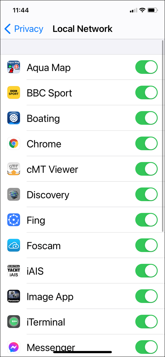
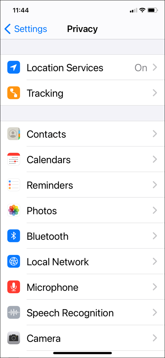
If you are using iOS 14 or higher, make sure the “Local Network” privacy settings are enabled for the app they want to use….
Go to Settings>Privacy>Local Network and make sure that the App is in the list and enabled….
3 – UDP or TCP?
Check what mode/protocol our product is set to, TCP or UDP (check product manual) and ensure that you set the same type of connection in the App. If the device is set to UDP and you try to use TCP in the App it will not work, both the device and app must be set to the same mode/protocol TCP or UDP. For TCP connections you need to enter an IP address of 192.168.1.1 and Port 2000, while for UDP you need to enter 0.0.0.0 and Port 2000, or if this fails try 192.168.1.1
4- App configured?
You must make sure that your app is configured. You should look at our section How to Configure Apps & Software to find out how to configure your navigation app.
5- GPS Settings
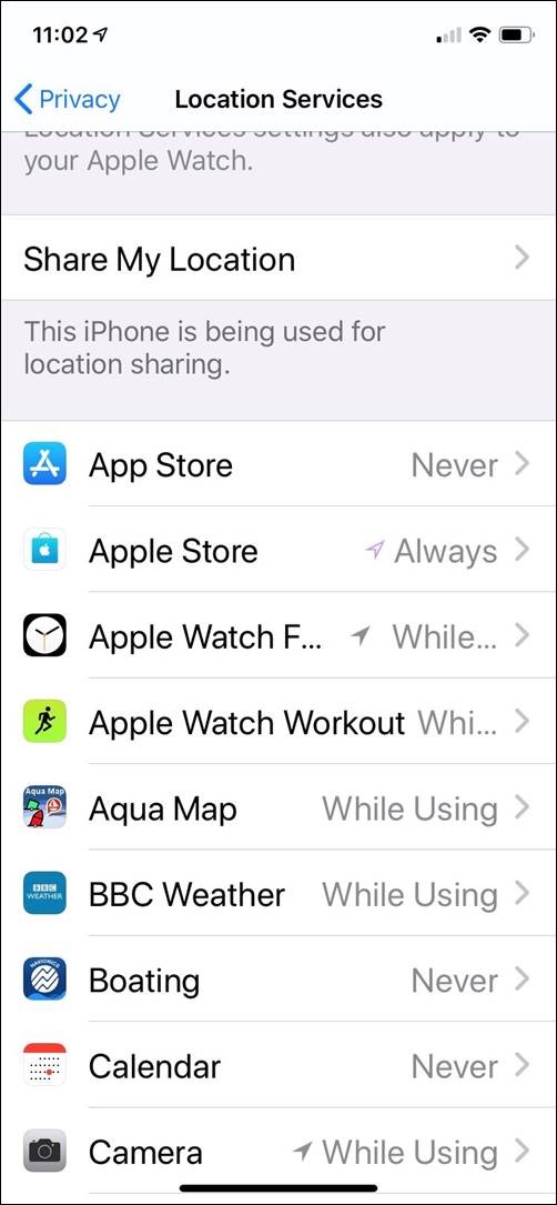
If you want the app to use the GPS data from the wireless connection, then go to Settings>Privacy>Location Services, on your iOS device and set the App to “Never” which will force the App to use the GPS position from the wireless connection, rather than try and use its internal GPS or even worse “Assisted GPS” if it is a Wi-Fi Only iPad.
How to manually reset an iAISTX?
This reset procedure just resets the iAISTX unit’s wireless interface and does not reset the MMSI number, which can only be carried out by an authorised dealer/distributor.
To reset the iAIS TX, you must open the product case by removing the 4 screws from the unit.
Once the screws have been removed, the base should be carefully disengaged from the top of the case using a small flat blade screwdriver.
There are interconnecting cables between the top and bottom of the case, so take care not to separate the two parts completely.
There is only one PCB inside and the PCB diagram is shown below with the JP1 connector that you need to short in red…
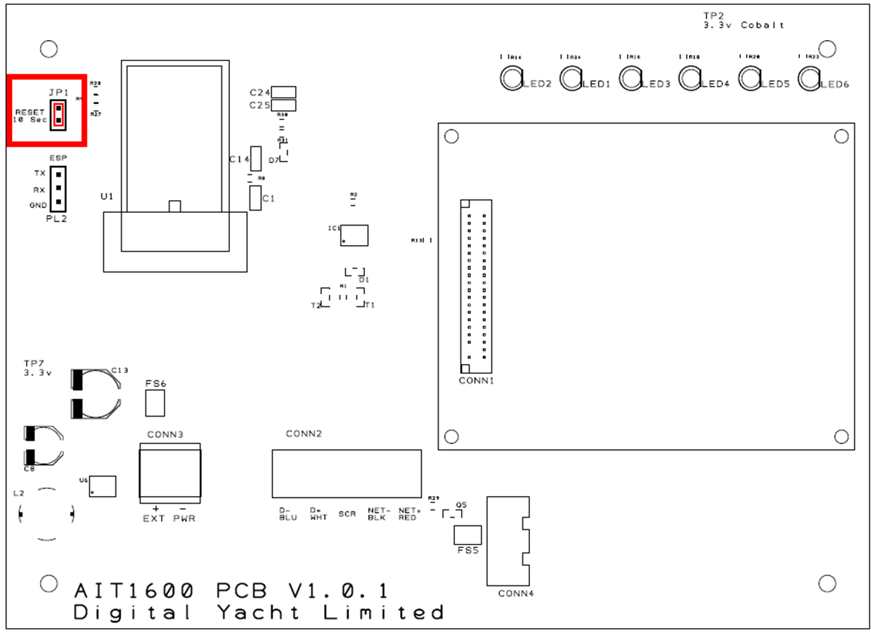
With the unit’s 12/24v DC power on, short the two pins of JP1 for at least 10 seconds (allow 15 seconds to be sure).
When you release, you should see the Wi-Fi and Data LEDs change flashing sequence slightly as the unit resets and reboots.
Once the iAISTX has rebooted, all of the wireless and web settings will be back to the factory defaults – as detailed in the user manual.
You should now be able to see the iAISTX-xxxx wireless network again. Try to get one of your devices to connect and stay connected to the iAISTX Wi-Fi connection.
Why my boat does not appear on MarineTraffic, VesselFinder, etc.?
- It is important for you to be aware of the limitations of these online sites. As a result, do not assume that you will always be picked up by them. Each of the different online services are only as good as their network of AIS receiving stations. In many cases, these shore stations are operated by AIS enthusiasts/volunteers who have a home/office by the sea. In many areas the coverage is great but there are definitely “holes” in coverage.
- One of the good features of the Marine Traffic service, is that you can display the locations of the receiving stations and see if they are currently online or offline. From the Marine Traffic home page, zoom in to your location on the map. Then on the left hand side of the screen, click on the “Layers” icon. This will show a series of tick boxes to display different layers of data will appear. Click the “Stations” tick box and you will see a series of Antenna type icons on the map; green if they are online (receiving data), red if they are offline and orange if they are online but giving poor reception performance.
- In the image below, you can see the the UK port of Exmouth. If you were testing your Class B transponder here today, then you would think you were not transmitting. Just one receiving station being offline can create a big hole in coverage and the next receiving station going East is Bridport around 35 miles away. This is a popular section of water and yet you can only see a few vessels between Torquay and Lyme Regis.
- A Class B transponder transmits at 2 Watts (about a third of the power of a hand held VHF). Therefore even in perfect line of sight conditions, the best range you can expect is about 8NM. It is important to check if there is a receiving station within 5-8NM of your location and if there are any other Class B vessels displayed near you.
- If you are more than 5-8NM from the receiving station or there is not a good clear line of sight between the station and your location, then your transmission is unlikely to be received.
- You should note that Commercial vessels and some larger pleasure craft have Class A Transponders. These transmit at 12.5 Watts and have a much greater transmit range 20-25NM. As a result, these vessels may be displayed near your location, even if your Class B transmission is not received.
- Finally, it can take an hour or so for a new AIS (MMSI number) to be recognised and stored in the database of these online services. Consequently, if you are confident that you are in range of an online receiving station, leave your transponder on for a few hours. This will give the online service time to detect and record you in their database.
ADDITIONAL NOTE
Another nice feature of Marine Traffic, is that you can drill down in to the details of a particular receiving station. Click on the icon of the Station of interest and a summary of the receiving Station’s information will be displayed. By clicking the Green “Details and Statistics” button, you can get a wealth of information about the station, its statistics and “live” AIS target reception list.
- As you can see, this particular station in Exmouth is regularly offline for quite long periods. Even when it is online, it has a rather poor 10NM reception range.
- For anyone that lives or has a business close to the sea and who would like to be part of an online AIS network, please contact us about our AISNet product, which can connect to your home/office network and put your local AIS reception data online.
Which VHF antenna for an AIS?
One of the most common questions we are asked by our AIS customers, is “what antenna should I use for my AIS ?”, so we thought we would post a short article to provide an answer on VHF Antenna Options for AIS.
Basically there are two VHF antenna options for AIS; fit a second dedicated VHF antenna a suitable distance from the vessels main VHF antenna. Or alternatively, use the main antenna for both VHF and AIS by fitting a special device called a “Splitter”.
Generally our recommendation for yacht owners who want to fit an AIS, is to use a “Zero Loss” splitter like our SPL2000. By utilising the main VHF antenna at the top of the mast, you will definitely get maximum transmit range. Plus the ease of installation often makes it a cheaper option than paying for a second antenna to be installed.
However, for power boaters who do not benefit from the height advantage of using the main antenna at the top of the mast. As well as for AIS receiver owners where the splitter can often cost more than the AIS receiver itself. It is often desirable to fit a second VHF antenna. This is particularly apparent if you intend to save money by doing the antenna installation yourself.
AIS operates on two dedicated channels within the marine VHF frequency range – 156.0 to 162.025 MHz. The two AIS channels are at the top end of this range namely; 161.975 and 162.025 MHz (channels 87B and 88B). Most VHF antennas are designed to give maximum gain across the whole VHF frequency range centred on Channel 16 (156.8 MHz).
Pretty much all of the antenna manufacturers now produce “AIS Tuned” antennas. These have their centre frequency shifted from Channel 16 to 162Mhz (exactly half way between the two AIS frequencies). If you choose to mount your AIS antenna on the stern rail of a yacht or radar arch of a power boat. Then using an “AIS tuned” antenna is a good idea. This will allow you to get an extra bit of gain. Thus compensating for the antenna being effectively at deck level.
The graph above shows how the tuning of the antenna to 162MHz gives it an extra boost in VSWR (gain) across the two AIS frequencies.
Which ever option you choose, having AIS on your boat will without doubt make your sailing experiences safer. As well as less stressful in poor visibility or when crossing busy shipping lanes. Even a simple receiver with a small whip antenna at deck level is effective. Allowing you to keep informed of what ships are around and which ones you need to keep an eye on.
AIS + VHF Antenna Separation
The AIS system works on two channels in the VHF frequency range and in order to receive or transmit AIS information it is necessary for the AIS unit to be connected to a VHF antenna. One option is to fit a VHF splitter such as our SPL2000, which allows both the VHF radio and the AIS to use the boat’s main VHF antenna. The other option is to fit a second VHF antenna which is then just connected to the AIS.
Any VHF antenna can be used, although some antennas are “AIS tuned” to get maximum gain on the two AIS channels and also have a BNC type connector fitted (common on AIS units), rather than the traditional PL259 VHF connector.
If you decide to fit an additional VHF antenna for the AIS, you want to mount it as high as possible but you should be aware that it cannot be mounted right next to the existing VHF antenna and a certain amount of separation must be maintained to avoid the 25 watts of transmit power from your VHF radio going straight in to the AIS receiver circuitry, potentially damaging it. The diagram below shows the recommended minimum separation of the antennas.
No GPS signal on an AIS Transponder due to loose FME connector
Our AIS transponders are supplied with a GPS antenna that has a 10m cable terminated in an FME connector (right hand connector in the above image).
These connectors are very slim, not much larger than the coax cable and are much easier to route through the boat. We also supply an FME to TNC adaptor for connecting the cable to the transponder (left hand connector in the above image).
Today we were reminded of the importance of ensuring this adaptor is firmly screwed on to the cable, when a US customer reported that their AIT2000 had stopped getting a GPS fix. After using the proAIS2 software to confirm that the GPS signals were very low, we asked the customer to check the GPS antenna connections to the AIT2000 and sure enough found that the FME connector had become loose and was no longer making a good connection.
A quick tighten of the FME connector in to the adaptor and the AIT2000 started to get a GPS fix again and the customer could continue their cruise.
The nut on the FME connector is 8mm (AF) and the TNC adaptor has two flat indents that are 9.5mm (AF). You can tighten the two connectors quite tightly but avoid using too much force which could damage the connector and cause a different set of problems. The image below shows the FME fully tightened in to the adaptor and there should be about a 1.5mm gap between the FME nut and the collar of the adaptor when properly tightened.
Our GV30 combo GPS and VHF antenna also uses FME connectors and is supplied with a TNC and BNC adaptor, which should also be tightened in the same way.
What’s the VSWR?
Checking the VHF/AIS Antenna, is the most difficult test. As a result, it is the one that we get the most technical support calls about. Therefore, we thought a blog post on the subject would help.
It is surprisingly common for yacht owners to install an AIS transponder with an antenna splitter and then find that their “old faithful” VHF antenna at the top of the mast is actually not as good as they thought it was. The reason for this, is that the top of the mast is a pretty hostile place. Over time, the antenna will suffer high levels of salt water and UV exposure, coupled with large temperature swings, vibration, G forces, etc. All of which start to degrade the materials and cabling. Alongside the occasional stepping of the mast, with possibly a through-deck connection or cable join inside the hull. You can see that there are lots of possibilities for the antenna to not be in tip-top condition.
All AIS transponders perform a continuous series of self tests, including a VHF antenna test. This is often the first time, in many years, that the VHF antenna at the top of the mast has been tested. Therefore, it is not unusual for some to fail the test. The reality is, that a VHF radio or AIS will happily get some level of reception even if you just connect a wire to it. As a result, you can appear to be receiving AIS data but your transmission is poor. This is due to an old/degraded VHF antenna that has a high Voltage Standing Wave Ratio (VSWR).
The VSWR of an AIS transponder, is a measure of the level of standing waves present in the antenna cable (feeder). Standing waves are the signals/power that do not radiate in to the air, by the antenna (load), but reflect back down the cable to the transponder (source). In an ideal world, all of the power sent to the antenna would transmit through the air to other vessels. However, this only happens if the impedance (AC resistance) of the source, feeder and load are identical (50 ohms).
This perfect matching of the impedances would result in a VSWR of 1:1. Although in “real life” pleasure boat installations, it is more likely to be between 1.1:1 and 2.5:1. In the diagnostic page of our proAIS2 software, the you can see the VSWR and will update upon every transponder transmission. By keeping an eye on the Transmit Counter you can see when a transmission takes place. You will probably see a slight change (in the decimals) each time the VSWR is measured, which is normal. If you see a bigger fluctuation, this is indicative of a poor connection or water ingress in the antenna cable/connections.
If the measured VSWR goes above 5:1, the RED Status LED will illuminate and a VSWR alarm displayed in proAIS2 (see top image).
Understanding the importance of having a good VHF antenna, with a low VSWR to get the best possible AIS transponder performance (transmit range) is key. We hope this article helps our customers have a better appreciation of this technology.
How to change the MMSI number?
Once entered and confirmed, the MMSI number on an AIS can only be changed by a technical dealer or by Digital Yacht. This is a government requirement in many countries to ensure the security of the AIS system.
If you need your MMSI number reset or changed, we offer a reprogramming service.
The cost for this is £65.00/75.00€ + Return Shipping (+VAT – if applicable)
If you would like to go ahead with this, please complete and print the following:
- AIS PROGRAMMING – for MMSI details.
- SERVICE RETURN FORM – for return shipping details.
If you do not have Microsoft Word or a means of editing Word documents, please print and complete this PDF version.
Please return the AIS transponder with the printed AIS PROGRAMMING form to the following address:
- USA/UK/ROW: Digital Yacht Service, 7 Farleigh Court, BS48 1UR, Flax Bourton, United Kingdom
- Europe/EU: Digital Yacht, 12 Boulevard des Belges, 76000 Rouen, FRANCE
If you’re returning a product from outside the EU, please put a value of GBP £10.00/ USD $14.00 / EUR €12.00 for the product and if requested by the freight company or postal service, use MARINE ELECTRONIC EQUIPMENT as a description and the commodity code 90148000.
The reason for return can be Product Service or Return for Repair.
Alternatively, the MMSI can be reset by any local NMEA certified/technical marine dealer who will have the cables, programming leads and software to complete.
For Nomad and Nomad2 customers, please contact us via our ticketing system.
What is the WiFi range/coverage of my product?
The Wi-Fi will typically footprint a boat up to 25m LOA. Contact us if you need a bigger footprint or have a steel or carbon vessel.
I have already a Wi-Fi router on board – can I join the product Wi-Fi to an existing network?
Yes! You can program this through the web interface so you just have one Wi-Fi network on board with our product linked directly to your other Wi-Fi network as a client.
This is explained in your product manual.
This works well as well with Furuno WiFi radar installations.
How to configure a navigation app or software?
We keep on our blog a list which explains how to configure all the popular navigation apps & software. This list explains how to configure a NMEA connection (UDP/TCP) on the app/software but also how to configure the AIS settings.
To see the list, please click here.
How many devices can connect to the WiFi network?
Up to 7 devices can connect using UDP. TCP/IP is a one to one connection format. PCs, MACs, Android, Linux and iPhone/iPad are all compatible.
What is the AIS transponder Wi-Fi network password?
Our AIS transponders with a built-in web interface create a password protected WiFi network. With your tablet, PC or smartphone, if you scan for wireless networks, you should see a wireless network called “DY-AIS-xxxx” or “IAISTX-XXXX” where xxxx is a four-digit code unique to your AIS transponder. The name of the WiFi networks might change according to the product version.
Make your device join this network and you will be asked to enter a password which is “PASS-xxxx” where xxxx is the same four-digit code as in your network name. You can change both the network name and password in the AIS transponder unit’s web interface.
For instance, if you have an AIT5000 and the WiFi network name created is DY-AIS-D4B7 then the WiFi network password is: PASS-D4B7
How to configure an AIS transponder with the web interface?
In order to facilitate the use and configuration of our AIS transponders, our new AIS transponders now have a built-in web interface. This is the case for the iAISTX, iAISTX Plus and AIT5000 (since March 2020). These devices create a WiFi network on board and configure themselves by connecting to WiFi.
The configuration of the transponder can therefore be done through a computer, a tablet or even a smartphone and most importantly, no software is required. Our other transponders can only be configured through a computer by connecting the USB and downloading a specific software (ProAIS2).
After installing and powering the device, here is the procedure to configure the AIS transponder through the web interface. The screenshots below use our old built-in web interface version.

1 – How to access the web interface
You need to connect to the WiFi network created by the AIS transponder (network name: DY-AIS-xxxx) . If the WiFi network has a password, then the password is: PASS-xxxx (xxxx is a 4-digit code unique to your device and is the same as the 4 digits on the WiFi network name).
Then, open a web browser (Safari, Chrome, Firefox, Edge, etc.) and either enter the IP address of the transpondeur…
http://192.168.1.1
…or if your device supports Bonjour/mDNS you can enter the following URL…
http://dy-ais.local
2 – Vessel details

This is the section in which you enter the MMSI and Static data to program the transpondeur. The MMSI number can only be programmed once, so particular care should be taken to check that it is correctly typed in. All other data can be changed at any time. You need to enter your boat dimensions and an approximative location of the GNSS antenna.
Once you are happy that all your boat’s static data has been entered correctly, remembering to double check the MMSI number, click the “Update Vessel Details” button and the details will be stored in the AIS unit.
3 – Vessel details

By default, the AIS transponder is in “Access Point” mode, that means it creates its own password protected wireless network and automatically provides network settings to any device that connects to it (via DHCP). You can change the default network name and password, if required, and the wireless channel that the unit uses (Channel 1 by default). For the rest of the network settings, we recommend that you do not change anything.
If you want to merge the AIS’s WiFi to an existing WiFi network on board, please read the unit manual.
Once everything is configured for the network settings, click on “Update Settings” button and the unit will save the new settings and restart (it takes about 30 sec).
4 – AIS Status and Silent Mode
By default, the AIS transponder is in “Access Point” mode, that means it creates its own password protected wireless network and automatically provides network settings to any device that connects to it (via DHCP). You can change the default network name and password, if required, and the wireless channel that the unit uses (Channel 1 by default). For the rest of the network settings, we recommend that you do not change anything.
If you want to merge the AIS’s WiFi to an existing WiFi network on board, please read the unit manual which you can download from here.
Once everything is configured for the network settings, click on “Update Settings” button and the unit will save the new settings and restart (it takes about 30 sec).
5 – View NMEA data and product firmware

Thanks to the web interface, you can also display the NMEA 0183 frames broadcast by the WiFi of the AIS transponder. You have to click on the “View data” button at the top of the web interface. If you have connected instruments to the NMEA 0183 input of the AIT5000, you will also be able to see the data of these instruments in this page.
At the bottom of the web interface, you can update the product when an update is available. Simply select the file in your computer or tablet with “Choose File” and then click on “Upload Firmware”.
AIT2500/AIT5000 – Disable NMEA 2000 GNSS PGNs
If you need to disable the GNSS PGNs that the AIT2500/AIT5000 outputs then this is the procedure to follow….
Using the proAIS2 software, go to the Serial Data tab and then copy and paste the following commands in to the box at the bottom of the page and click the “Send” button (see image below).
- To disable GPS data output over NMEA 2000 send this command:
$PSMT,0,3,0x2C75B2FA,1,n2kognss 0,0*15
- To enable it again send this command:
$PSMT,0,3,0x2C75B2FA,1,n2kognss -1,0*39
….if the command was successfully received and actioned, you should see Transponder respond with…
- $PSMT,255……….etc. (basically, the same as the command but 255 instead of 0 after the $PSMT, text)
How to install the AIT5000?
This video will show you how to install our AIT5000 Class B+ AIS Transponder for NMEA 0183 & NMEA 2000 based systems.
To configure the AIT5000, you need to configure the AIT5000 with its built-in web interface.
AIS Receiver (AIS100, AISNode)
I cannot display AIS targets
If you encounter an issue with AIS showing on your display (navigation software or chart Plotter) then you should follow this procedure.
1 – Issue with a Chart Plotter/VHF Radio
If you cannot display AIS targets on your Chart Plotter or VHF radio, then follow this:
- If you have connected your AIS to your Chart Plotter/VHF Radio via NMEA 0183 wires, then you must make sure that you have used the NMEA 0183 38400 baud wires (Orange + & Brown – for Digital Yacht AIS Transponders). The second step is to check your Chart Plotter / VHF Radio settings. The best solution here is to check your product manual but you must make sure that the NMEA 0183 port is set at 38400 baud and also that AIS targets are activated.
- If you have connected your AIS to your Chart Plotter/VHF Radio via NMEA 2000, then you must make sure that the NMEA 2000 network is working properly. This page might answer to your question. You should also make sure that AIS targets are activated in your chart plotter / VHF radio settings.
2 – Issue with a Navigation Software / App
If you cannot display AIS targets on your navigation software or app then follow this:
- For an Android/iOS app: The first step is to make sure that all apps are closed in the background, then you are connected to the product WiFi network. The second step is to configure your navigation app. This is explained in this page.
- For a PC Navigation Software: The first step is to make sure that the USB drivers are installed. You can download them here if needed. You must then find out the port COM allocated to your USB port. The last step is to configure your navigation software. This is explained in this page.
I don’t have a good AIS range
AIS Transmission/Reception depends on the AIS Class
- A Class B AIS transponder transmit at 2 watts whereas a Class A Transponder at 12.5 watts. The Class B+ SOTDMA transponder transmits at 5 watts. This difference in power has a huge impact on the transmission range of each transponder.
- For a Class B AIS transponder, the transmission range is usually 5 to 7 miles in perfect conditions. This means using a good VHF antenna, placed as high as possible and clear of other antennas. The cables and connectors must also be in good conditions. For a Class B+ 5W SOTDMA, it typically transmits at up to 15 miles.
- However, for the AIS reception, a Class B/Class B+ transponders can receive Class A AIS at up to 30 miles.
If you don’t have a good range
- If you are using a VHF antenna splitter for your transponder, make sure it is a ZeroLoss VHF Splitter like our SPL1500, SPL2000. You must also check the connectors and the cables between the VHF splitter and the AIS.
- If you are using a dedicated VHF antenna for your transponder, then make sure that it is at least 2 meters away from other VHF antennas. Also, you must check the VHF antenna, its cable and connectors.
If you don’t have a good range, we suggest you testing with another VHF aerial to check if you have a better range.
Which VHF antenna for an AIS?
One of the most common questions we are asked by our AIS customers, is “what antenna should I use for my AIS ?”, so we thought we would post a short article to provide an answer on VHF Antenna Options for AIS.
Basically there are two VHF antenna options for AIS; fit a second dedicated VHF antenna a suitable distance from the vessels main VHF antenna. Or alternatively, use the main antenna for both VHF and AIS by fitting a special device called a “Splitter”.
Generally our recommendation for yacht owners who want to fit an AIS, is to use a “Zero Loss” splitter like our SPL2000. By utilising the main VHF antenna at the top of the mast, you will definitely get maximum transmit range. Plus the ease of installation often makes it a cheaper option than paying for a second antenna to be installed.
However, for power boaters who do not benefit from the height advantage of using the main antenna at the top of the mast. As well as for AIS receiver owners where the splitter can often cost more than the AIS receiver itself. It is often desirable to fit a second VHF antenna. This is particularly apparent if you intend to save money by doing the antenna installation yourself.
AIS operates on two dedicated channels within the marine VHF frequency range – 156.0 to 162.025 MHz. The two AIS channels are at the top end of this range namely; 161.975 and 162.025 MHz (channels 87B and 88B). Most VHF antennas are designed to give maximum gain across the whole VHF frequency range centred on Channel 16 (156.8 MHz).
Pretty much all of the antenna manufacturers now produce “AIS Tuned” antennas. These have their centre frequency shifted from Channel 16 to 162Mhz (exactly half way between the two AIS frequencies). If you choose to mount your AIS antenna on the stern rail of a yacht or radar arch of a power boat. Then using an “AIS tuned” antenna is a good idea. This will allow you to get an extra bit of gain. Thus compensating for the antenna being effectively at deck level.
The graph above shows how the tuning of the antenna to 162MHz gives it an extra boost in VSWR (gain) across the two AIS frequencies.
Which ever option you choose, having AIS on your boat will without doubt make your sailing experiences safer. As well as less stressful in poor visibility or when crossing busy shipping lanes. Even a simple receiver with a small whip antenna at deck level is effective. Allowing you to keep informed of what ships are around and which ones you need to keep an eye on.
AIS + VHF Antenna Separation
The AIS system works on two channels in the VHF frequency range and in order to receive or transmit AIS information it is necessary for the AIS unit to be connected to a VHF antenna. One option is to fit a VHF splitter such as our SPL2000, which allows both the VHF radio and the AIS to use the boat’s main VHF antenna. The other option is to fit a second VHF antenna which is then just connected to the AIS.
Any VHF antenna can be used, although some antennas are “AIS tuned” to get maximum gain on the two AIS channels and also have a BNC type connector fitted (common on AIS units), rather than the traditional PL259 VHF connector.
If you decide to fit an additional VHF antenna for the AIS, you want to mount it as high as possible but you should be aware that it cannot be mounted right next to the existing VHF antenna and a certain amount of separation must be maintained to avoid the 25 watts of transmit power from your VHF radio going straight in to the AIS receiver circuitry, potentially damaging it. The diagram below shows the recommended minimum separation of the antennas.
CLA2000
CLA2000 – “The Modem is not responding” Message during installation
If you see the “Modem Not Responding” error on a CLA2000, then it indicates that the 120 Ohm resistors are not fitted to the six NMEA 0183 Inputs and electrical noise at power up, causes the main processor to think the modem has a problem.
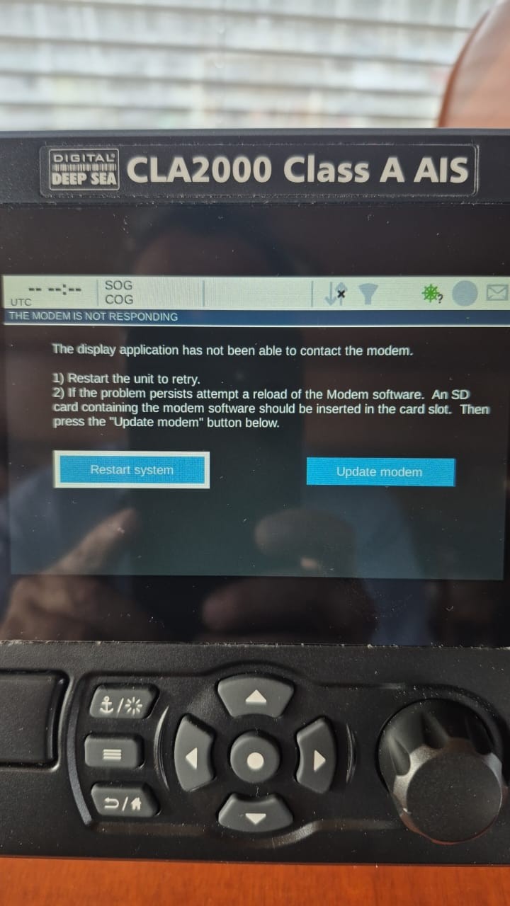
There are three inputs on the 18 Way Connector and if you have the 14 Way connector fitted, then there are additional three inputs on this cable as well – see the connection tables below, where the six NMEA 0183 Inputs are highlighted by red rectangles.
Simply connect a 120 Ohm resistor between the RX A and RX B wires on each of the six inputs. You only need to fit the resistors to the inputs of the cables that are attached to the CLA2000 and if you have the optional Connection Box fitted, these resistors are pre-installed in the box and no additional resistors are required. A pack of six resistors (see image below) are included in every CLA2000 package.
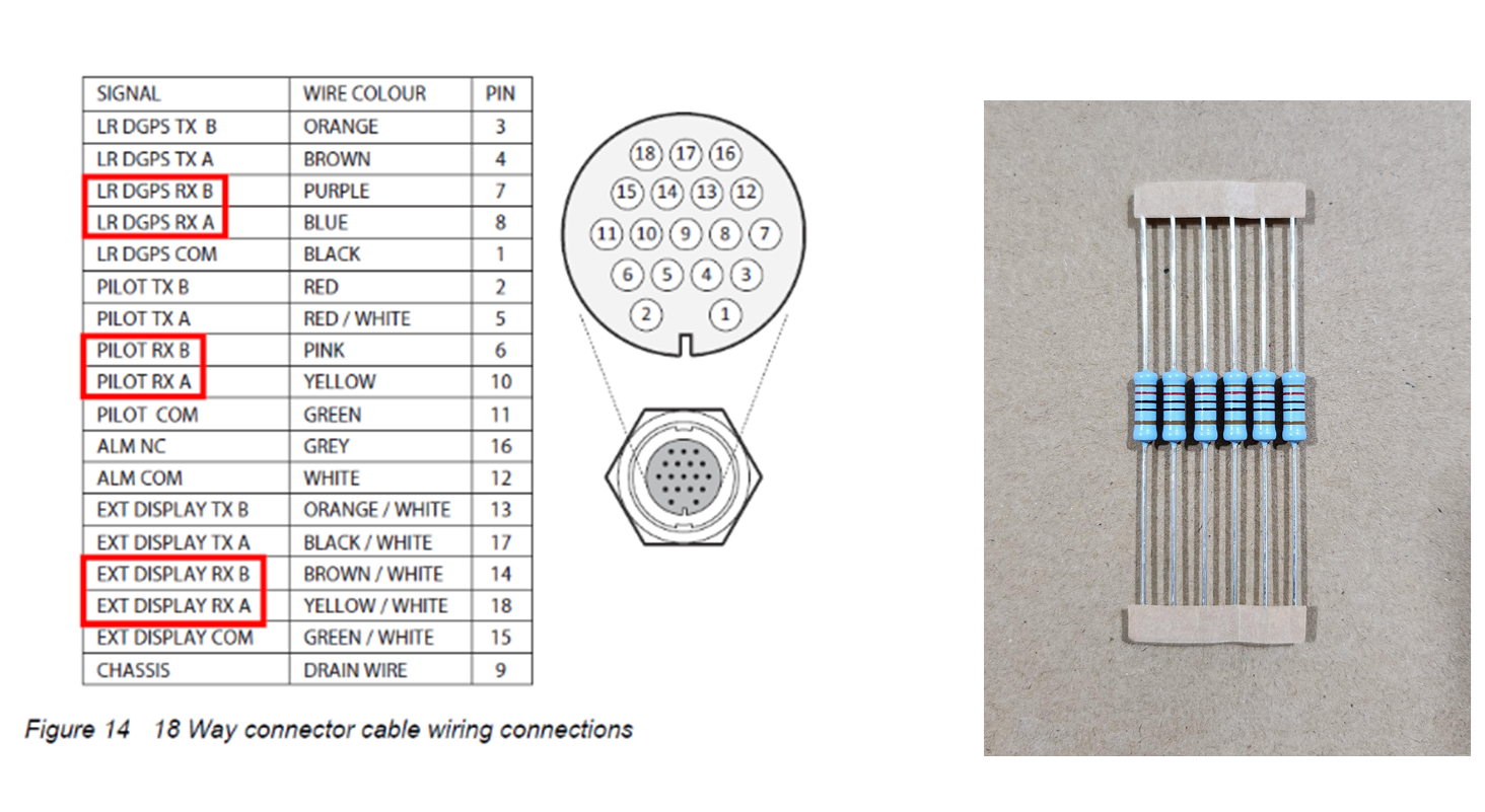
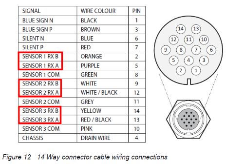
If the error is not resolved by following the above, please contact us again.
SPL1500 & SPL2000
Will my VHF radio receive signals even if the splitter/AIS is turned off?
Our AIS Splitters; SPL1500 and SPL2000 and also our AIT3000 and AIT5000 transponders that have built-in splitters. They are all designed so that in the case of failure or when the power is turned off, that the antenna is connected to the VHF radio.
This fail safe mode of operation is a key feature of the splitter design and gives owners the peace of mind that the antenna is always connected to their VHF, except when the AIS is transmitting which takes just 28 milliseconds and is undetectable even when listening or talking on the VHF.
Connecting FM Radio to the VHF Splitter
A coax cable has an inner wire and then the braided shield and a quick and easy way is just to strip the cable back and solder or join using terminal block the Inner wire to the Orange wire and the Outer shield to the Green wire.
However, if you want to make a nicer, more robust solution, you could get one of these…
https://www.adafruit.com/product/2889
and one of these…
Then the Orange wire would go in the + screw terminal and the Green in the – screw terminal. The BNC connector would be crimped on to the coax cable and you end up with a much more longer lasting connection.
Which VHF antenna for an AIS?
One of the most common questions we are asked by our AIS customers, is “what antenna should I use for my AIS ?”, so we thought we would post a short article to provide an answer on VHF Antenna Options for AIS.
Basically there are two VHF antenna options for AIS; fit a second dedicated VHF antenna a suitable distance from the vessels main VHF antenna. Or alternatively, use the main antenna for both VHF and AIS by fitting a special device called a “Splitter”.
Generally our recommendation for yacht owners who want to fit an AIS, is to use a “Zero Loss” splitter like our SPL2000. By utilising the main VHF antenna at the top of the mast, you will definitely get maximum transmit range. Plus the ease of installation often makes it a cheaper option than paying for a second antenna to be installed.
However, for power boaters who do not benefit from the height advantage of using the main antenna at the top of the mast. As well as for AIS receiver owners where the splitter can often cost more than the AIS receiver itself. It is often desirable to fit a second VHF antenna. This is particularly apparent if you intend to save money by doing the antenna installation yourself.
AIS operates on two dedicated channels within the marine VHF frequency range – 156.0 to 162.025 MHz. The two AIS channels are at the top end of this range namely; 161.975 and 162.025 MHz (channels 87B and 88B). Most VHF antennas are designed to give maximum gain across the whole VHF frequency range centred on Channel 16 (156.8 MHz).
Pretty much all of the antenna manufacturers now produce “AIS Tuned” antennas. These have their centre frequency shifted from Channel 16 to 162Mhz (exactly half way between the two AIS frequencies). If you choose to mount your AIS antenna on the stern rail of a yacht or radar arch of a power boat. Then using an “AIS tuned” antenna is a good idea. This will allow you to get an extra bit of gain. Thus compensating for the antenna being effectively at deck level.
The graph above shows how the tuning of the antenna to 162MHz gives it an extra boost in VSWR (gain) across the two AIS frequencies.
Which ever option you choose, having AIS on your boat will without doubt make your sailing experiences safer. As well as less stressful in poor visibility or when crossing busy shipping lanes. Even a simple receiver with a small whip antenna at deck level is effective. Allowing you to keep informed of what ships are around and which ones you need to keep an eye on.
S1000
How to test the S1000 AIS SART?
The AIS SART should be tested annually to confirm correct operation. In order to maximise the available battery capacity it is not recommended to test the AIS SART more frequently. Carry out the following steps to test the AIS SART:
- Remove the AIS SART from the bracket or bag and move to an outdoor location with a clear view of the sky. Do not hold the AIS SART in the location marked over the internal GPS antenna.
- Press and hold the ‘Test’ button for three seconds until the indicator starts flashing. The test is now active and the AIS SART will attempt to obtain a GPS position fix for five minutes.
- The outcome of the test is indicated as shown in Figure 11. During the test AIS messages are transmitted and will be received by all nearby vessels. Refer to section 4.5 for further information on display of AIS SART position and messages on other equipment.
- If a pass is not indicated by the end of the test period then the AIS SART should be relocated and the test repeated.
- If battery expiry is indicated please contact your dealer to arrange for battery replacement. Section 5 provides further details on battery replacement.
The AIS SART test can be cancelled at any time by pressing and holding the ‘Test’ button for three seconds. The indicator will extinguish when the test has been cancelled.
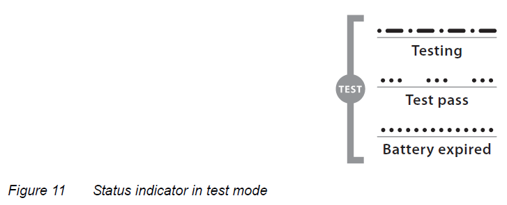
Internet on Board
NeXuX Connect / 4G Xtream / 5G Xtream
Slower speeds when StarLink is active?
Both the WAN port and the 3 x LAN Ports on our NeXuX are 10/100/1000Mbps ports and if connected to another 1000Mbps wired Ethernet device will pass data at 1000Mbps (1Gb).
A wireless device on the network will not achieve anywhere near 1000Mbps and depending on whether you are using the 2.4GHz or 5GHz wireless network, will only achieve around 50Mbps to 150Mbps. Please note that wireless devices share the maximum bandwidth that the wireless technology supports, so more wireless devices = slower speeds.
Other issues that can affect wired transmission speeds are; quality and condition of the network cabling – best to use Cat6 cabling as although a Cat5e cable can support 1000Mbps, it lacks any redundancies in grounding, which is a common point of failure in network cables. Also if you have a network switch plugged in to the router to provide extra ethernet sockets and that is only 10/100 it will slow down all devices that are plugged in to it.
If you have any speed critical devices like Smart TVs, streaming devices, etc. I would recommend plugging these directly in to one of the 3x LAN sockets on the NeXuX using Cat6 cable and you should achieve maximum throughput of data, up to whatever speed the StarLink antenna can provide in that location/time period.
How to configure the LAN port address?
To change the IP address range used on the LAN network, go to NETWORK>LAN and then click the EDIT option. Set as shown below and click SAVE&APPLY. When the unit reboots, reconnect and access the web interface at the address you have set. In the example below, we have set the addres: 172.31.0.1 so when we reboot the unit, to access the web interface in our example, we need to write the address http://172.31.0.1
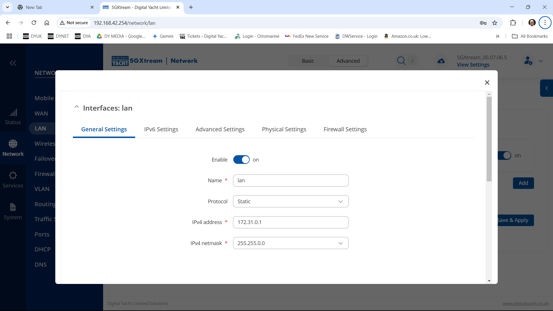
The DHCP range is set automatically, but if they want to check or change this, go back to NETWORK>LAN and click EDIT and the DHCP settings are in the Firewall Settings tab.
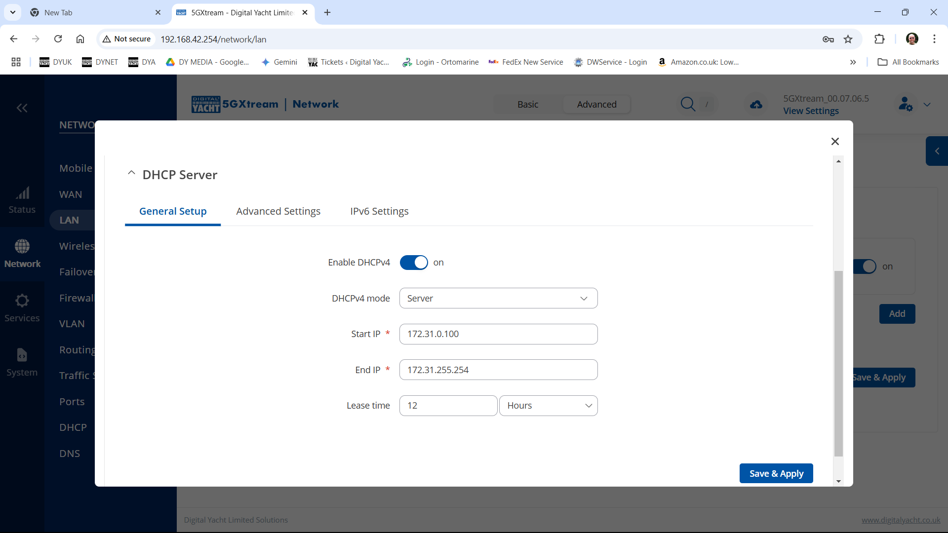
Using the 4GXtream’s GPS on the NMEA 2000 network
Applicable to 4GXtream units with NMEA 2000 interface
In order to direct the 4GXtream’s internal GPS data to it’s internal NMEA 2000 gateway, we must create a TCP network connection between the two devices.
- In the 4GXtream’s web interface go to SERVICES>GPS>GENERAL and enable the settings as shown below and click SAVE & APPPLY…
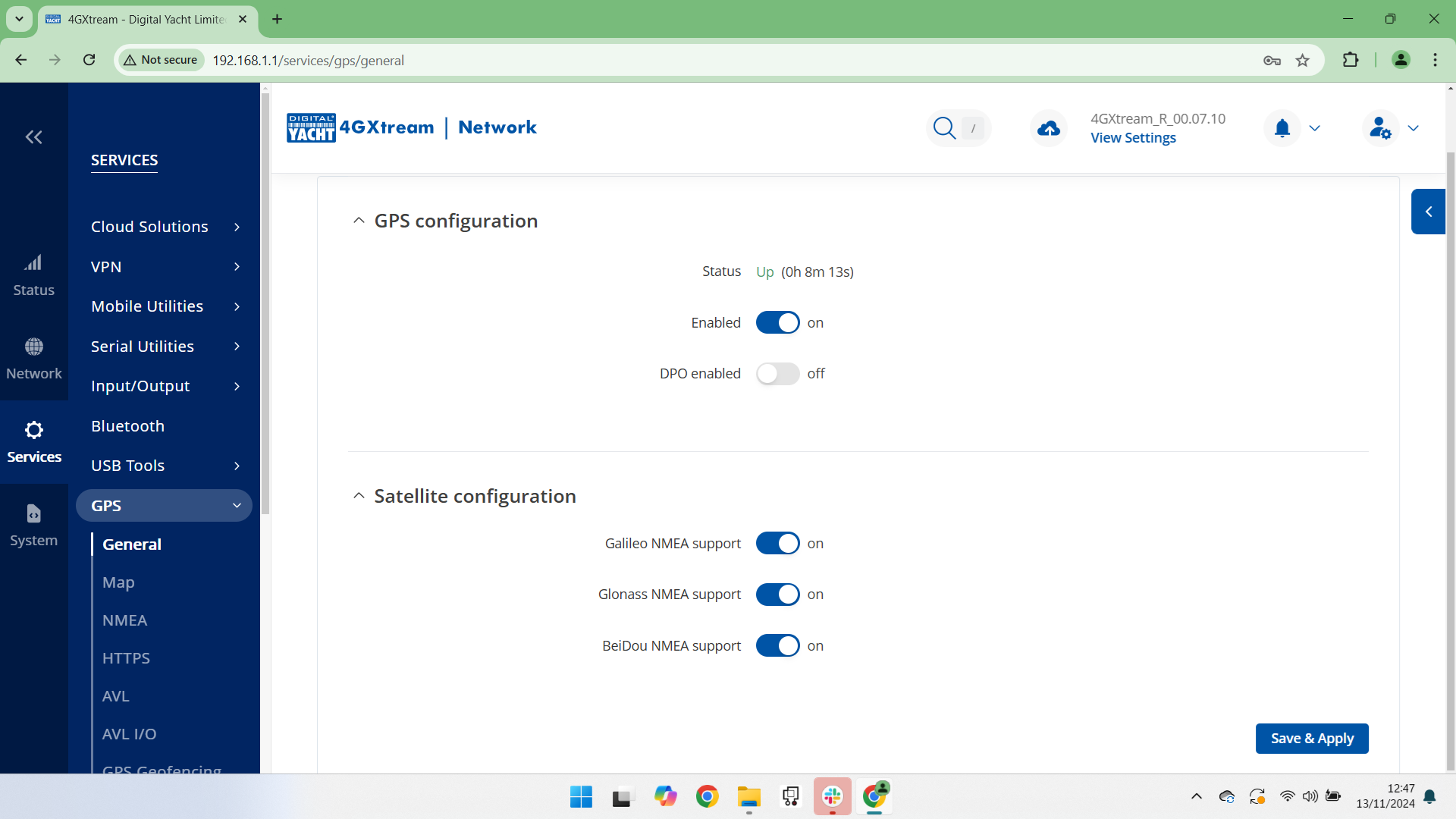
- Now goto SERVICES>GPS>NMEA and setup the NMEA Forwarding as shown below….
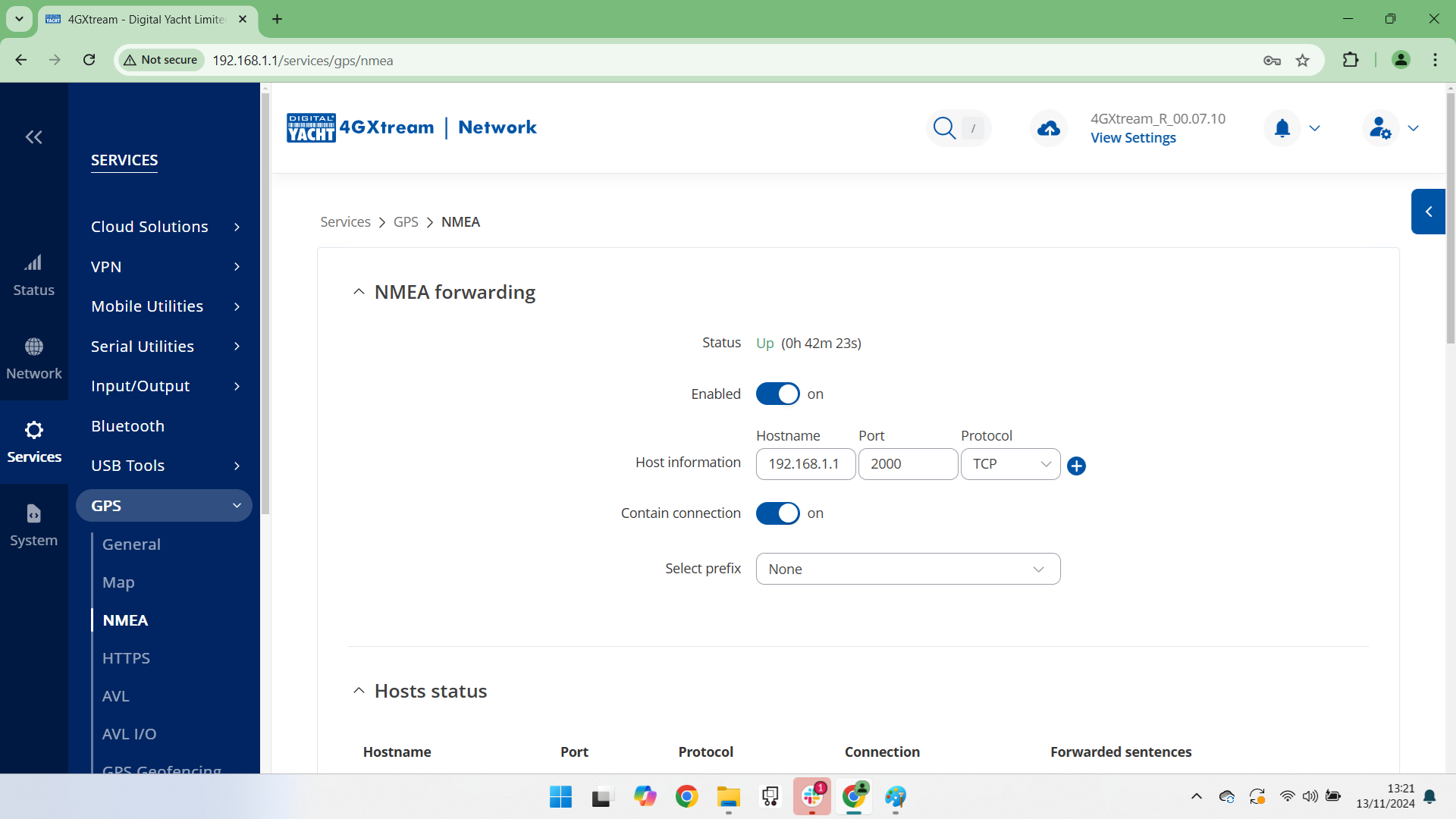
- Scroll further down the page and turn on the GPRMC sentence to be transmitted every 1 second and click SAVE & APPLY…
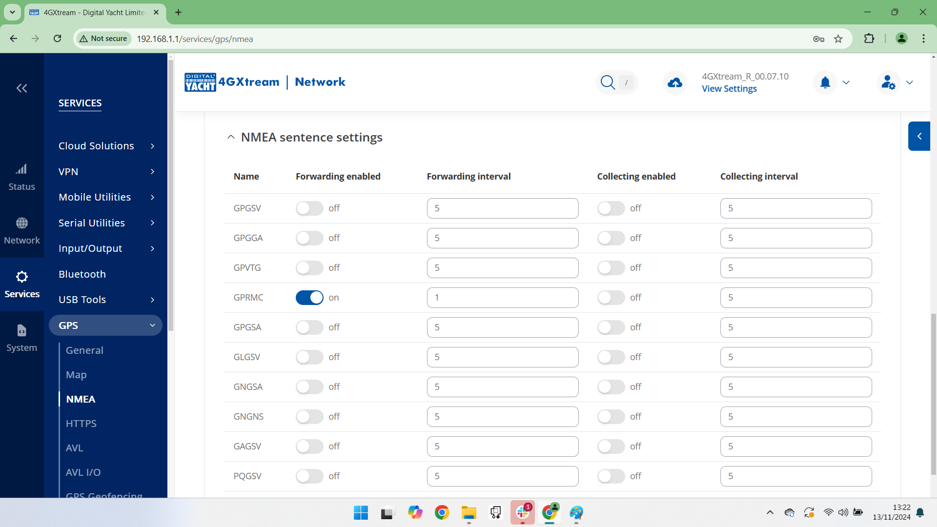
- Now goto SERVICES>SERIAL UTILITIES>OVER IP and Edit the iKonvert entry. Make sure that the iKonvert is being detected, it should say usb_serial_xxxxxxxx where xxxxxxxx is the serial number of your device.
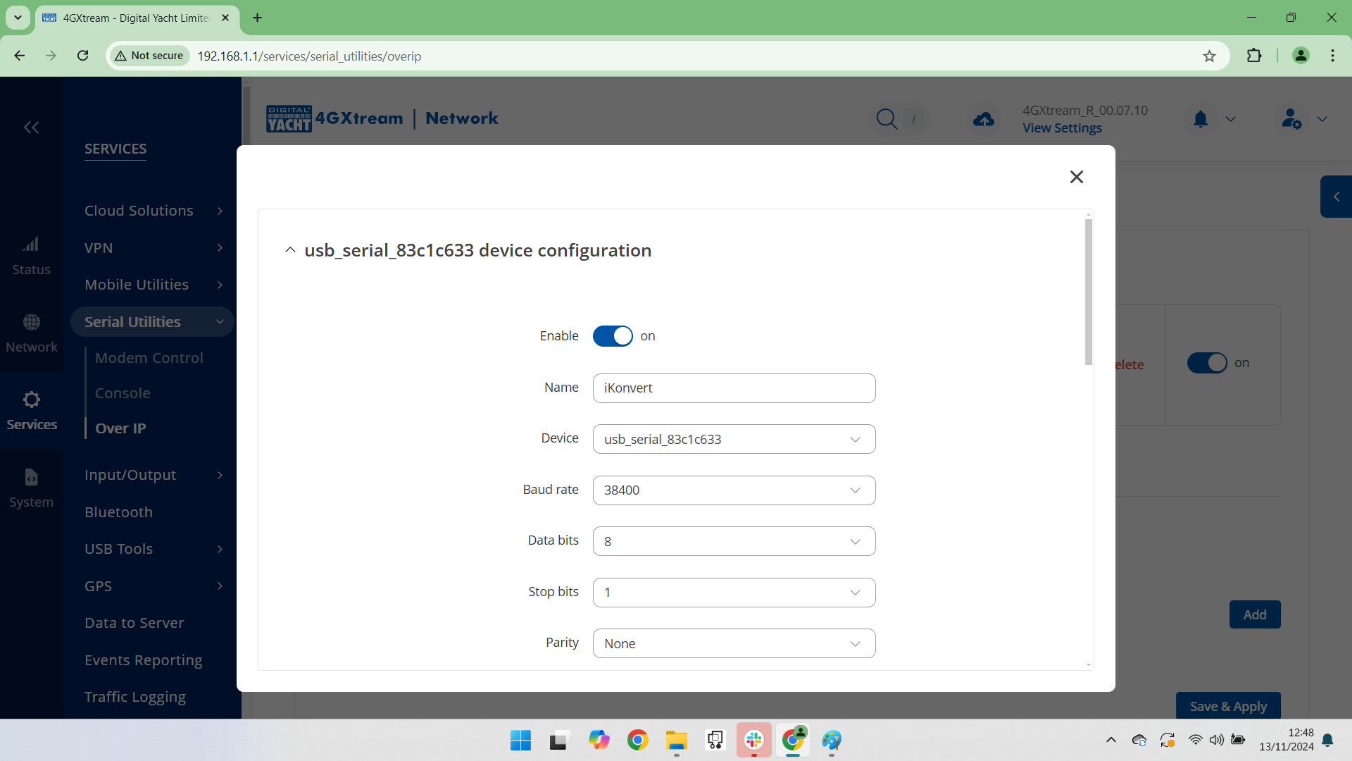
- Scroll down this page and set the settings shown below and then click SAVE & APPLY…
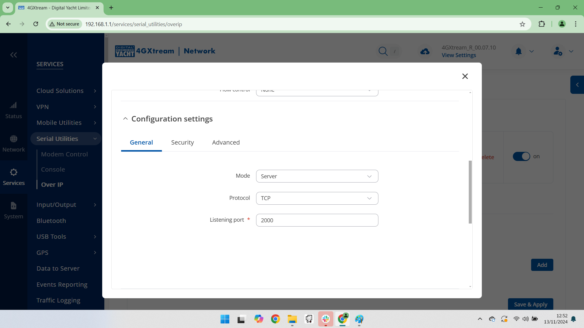
- If GPS data is being received and transmitted to the iKonvert for converting to NMEA 2000, you will see one Connected Client and the RX and TX counters will start to increment….
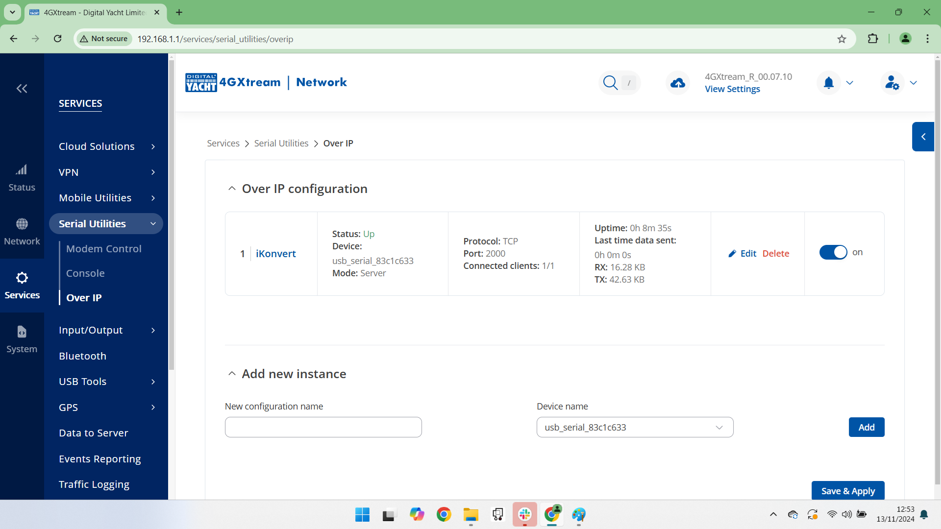
Now you should have the 4GXtream’s GPS data on the NMEA 2000 network.
How to set up 4G/5G Xtream failover mode with Starlink
Testing and Configuring the NAVAlert SMS Feature with 4G/5G Xtream
On the router, in Advanced mode go to SERVICES>MOBILE UTILITIES>SMS GATEWAY and check if there is a Username setup called NAVAlert….
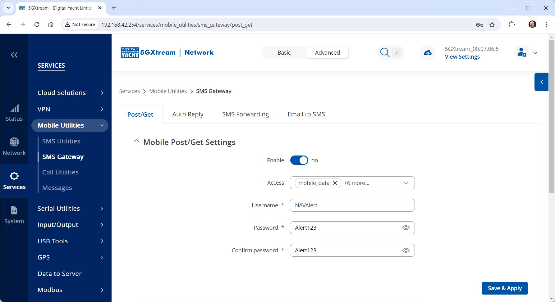
If there is not, then create one and if there is, please set the Password to Alert123 in both boxes and click the SAVE&APPLY button.
Now open a new browser window and copy and paste the following link into the Address bar….
You should see an OK page appear and after a few seconds receive an SMS on your mobile….ignore my IP address and Mobile number which are different to yours.
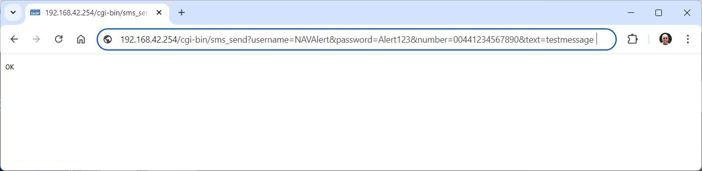
This proves that the 4GXtream is configured OK for SMS.
Now let us turn our attention to the NAVAlert.
Please can you enter your mobile number pre-fixed with your country code i.e. 0033617812887 in the NAVAlert SMS field. If you have a button just to select 4GConnect or 4GXtream, then you do not have the latest firmware. You can either update your NAVAlert unit’s firmware, I will need to send this to you tomorrow as our developer is out of the office today, or you can go back to the SMS Gateway page on the 4GXtream and change the password of the NAVAlert Username to the original password = Alert and then click the Send Test SMS button.
Powering Starlink antenna when connected to 4G/5G Xtream
Switching SIM cards automatically or manually
The 4G /5G Xtream has two SIM card slots which can be manually switched between, or you can use the automatic SIM switch feature to automatically switch between them. When the automatic SIM switching feature is enabled, the 4G/5G Xtream will monitor the current SIM network and if a certain condition occurs, it will switch to using the other SIM network as detailed below.
The SIM Switch section provides you with the possibility to configure SIM switching rules, i.e., set up circumstances under which the device will perform a switch from using one SIM card to another. Refer to the figure and table below for information.
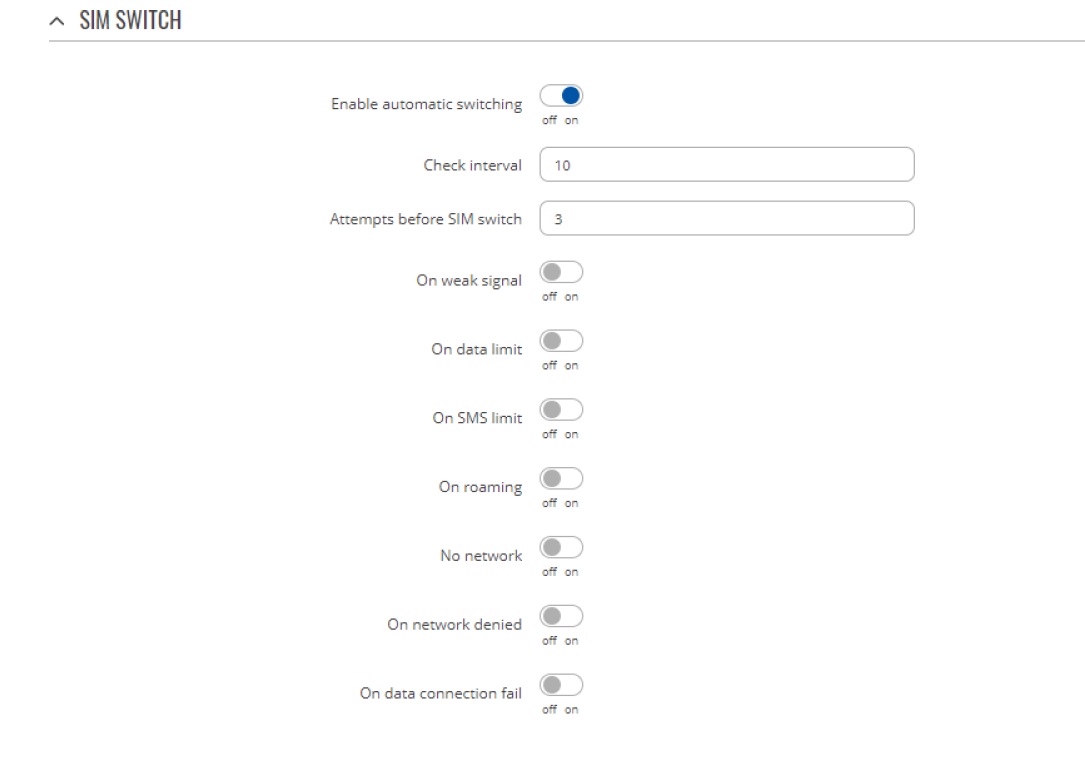
| Field | Value | Description |
| Enable automatic switching | off | on; default: off | Turns automatic SIM switching on or off. |
| Check interval | integer [3..3600]; default: 10 | The frequency (in seconds) at which the device will check for SIM switch conditions. If such a condition exists, the router will perform a SIM switch, if not – it will check for the same conditions again after the amount of time specified in this field passes. |
| Attempts before SIM switch | integer [1..10]; default: 3 | How many times a condition will be checked before executing a SIM switch. For example, if the device is a state that meets at least one SIM switch condition, the device will perform a number of additional checks specified in this field and will perform a SIM switch only if the condition is met on every check. |
| On weak signal | off | on; default: off | Performs a SIM switch when the signal strength drops below a certain threshold. |
| On data limit | off | on; default: off | Performs a SIM switch when the mobile data limit for this SIM card is reached. You can set up a mobile data limit in the Network → WAN (Basic WebUI mode) or Network → Interfaces (Advanced WebUI mode) pages by clicking ‘Edit’ next to the interface you wish limit the data for. |
| On SMS limit | off | on; default: off | Performs a SIM switch when the SMS limit for this SIM card is reached. You can set up SMS limit in the Network → Mobile → General page. |
| On roaming | off | on; default: off | Performs a SIM switch when roaming conditions are detected. |
| No network | off | on; default: off | Performs a SIM switch when a network connection is not available. |
| On network denied | off | on; default: off | Performs a SIM switch when access to a network is denied by an operator. |
| On data connection fail | off | on; default: off | Performs a SIM switch when mobile data connection fails. Possible failure determination methods are:
• • LCP echo • • ICMP echo
If no echo is received, the data connection is considered to be down. |
When configuring SIM switching from the Secondary card, an additional field called “Switch back to primary SIM card after timeout” becomes available:

| Field | Value | Description |
| Switch back to primary SIM card after timeout | yes | no; default: no | Attempts to switch back to the primary SIM card once the specified period of time passed. |
| Initial timeout (min) | integer; default: 1 | Indicates a time value (in minutes) after which the device will attempt to switch back to the primary SIM card. |
Setting up an anchor alarm with 4G Xtream / 5G Xtream
Slow internet speed through WiFi on my 4G Router
If you have a very low internet speed (less than 5m/sec) then several factors can interfere with your internet speed.
When a device is connected to one of our wireless 4G routers, the router has to “route” the data, which takes time. The typical 2.4GHz speed of 50Mbps is shared across all devices on the wireless network: more devices, less speed
It is not uncommon for other 2.4GHz wireless networks to be present on a modern boat; MFD, Charger/Inverter, AIS, etc. Each network, will potentially cause interference and slower speeds
To get a better speed, the best solution is to connect your laptop via Ethernet. With the 4G Connect Pro, you can get internet up to 60m/s via Ethernet but via WiFi, a good connection would be 25-35Mbps.
- The first step is to check all your installation. Make sure there is no interference with your device’s 4G antennae (a nearby radar, for example). Antenna height is not as critical as VHF and better to mount lower and not increase antenna cable length. If installation demands longer cables we can supply 10m or 20m LMR400 cable assemblies. Don’t extend the standard 7m LMR200 cables.
- Then, you should run a speed test on a wired device. Connect a device to the LAN socket of the 4GConnect via a network cable – this gives maximum speed and then do a speed test.
- Another action is is to do a Wi-Fi Survey to see if you are getting interference and congestion. An external Wi-Fi network might interfer with your 4G router network and affect your internet speed. You can do a Wi-Fi survey test with the following article.
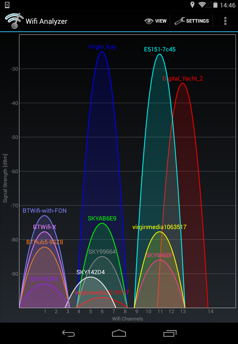
4G Xtream WiFi / GPS / Bluetooth antenna layout
The Bluetooth connector that is not currently used for any marine applications is a Reverse Polarity SMA connector and should be identical to the two Wi-Fi antenna connectors.
The GPS antenna is a standard SMA connector and the supplied GPS antenna should plug straight in with no additional adaptors required.
Below is an image showing the 4GXtream connectors, that you can use to check against your unit.
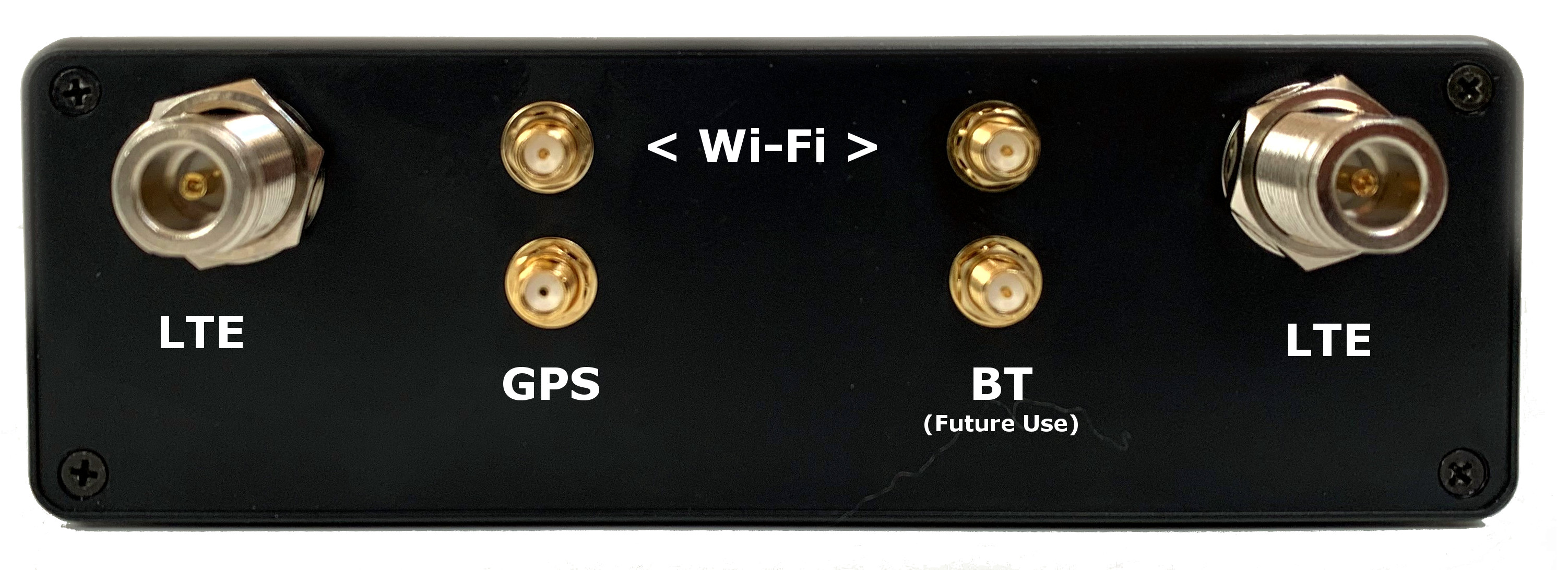
How to use a Starlink Dish with the 4GXtream as the main router?
You will need a StarLink Ethernet Adaptor, like the one below:
https://www.starlinkhardware.com/starlink-ethernet-adapter-setup-and-review/
Then using a normal network cable, you need to plug the Ethernet Adaptor in to the WAN socket of your 4GXtream and set the Wired WAN as the highest priority WAN connection. You can use the Failover feature of the 4GXtream to make it switch to Mobile (4G) when Starlink is not connected to the internet.
Finally and most importantly, you need to Enable Bypass Mode in the Starlink.
- Open up the Starlink app
- Tap Settings
- Swipe down and tap Bypass Mode
- Slide the toggle to the right
- When prompted, confirm you want to continue by tapping OK
Even though the Starlink router is now in bypass mode, you can still access most of the dish settings from either the app, or the Starlink web interface. You’ll need to be on a device that is connected to your 4GXtream. If you aren’t familiar with the web interface, it can be accessed from a web browser by visiting:
or
Why isn’t my new 4GXtream connecting to the internet?
When you scan for wireless networks on whatever mobile device you are using, can you see the 4GXtream wireless network?
If you can, please connect to it using the default wireless password = 4GXtream
Once you are wirelessly connected to the 4GXtream, then please open your web browser in a Private/Incognito window (important so that it does a fresh load of the 4GXtream web interface) and then try to go to http://192.168.1.1 or http://4gxtream
Whichever, address you use, it is very important that you include the http:// as this tells your browser that you want to go to a specific address and not do a Google search on 192.168.1.1 or 4gxtream
This must work as it is a core feature of the 4GXtream and will have been tested during production.
Assuming that you can now bring up the 4GXtream web interface, we need to check the main STATUS>OVERVIEW page.
Most of the time 4GXtream will connect to the SIM operators APN settings automatically, but some networks we still have to manually enter the APN settings. To find your SIM’s correct settings, please check out this website: https://www.apnsettings.org/ The 4GXtream runs on Linux, which uses Android underpinnings, so make sure that the APN settings are for Android use.
Please also note that the PDP type should always be set to IPv4 only and when Googling the APN settings, ignore the older MMS and WAP settings, it needs to be the LTE/4G settings.
4G Xtream and potential DHCP clashes with my MFD?
In general, unless indicated differently by the MFD manufacturer (Navico/Garmin/Raymarine/Furuno), it is best to leave the manufacturer’s wired Ethernet network, just for connecting the manufacturer’s equipment together and if you want to provide the system with an internet connection, to do this by connecting the master MFD wirelessly to our 4GXtream.
This will result in having two wired Ethernet networks on the boat, one for the navigation equipment and the other for internet access and normal IT type networking, but it will result in the most reliable operation of the two networks.
Most MFD manufacturers do not want customers to open up their Ethernet network to either a conventional LAN or WAN environment that they have no control over. Unknown network devices, levels of network data and protocols, that the manufacturer has never tested against, could potentially have serious, negative effects on the operation of their equipment.
The MFD’s wireless interface will be on a separate subnet and “locked down” so that it just does what they need it to do and no more. When you tell the wireless interface to join another wireless network in STATION (STA) mode, rather than its default ACCESS POINT (AP) mode, it will get an IP Address for the wireless interface from the 4GXtream and be able to go online for updates, weather data, etc.
Starlink and 4GXtream
You will basically be plugging the Star Link in to the WAN socket of the 4GXtream and then using the web interface to switch between the wired WAN interface (Star Link) and the 4G Mobile interface.
There is a “Failover” mode in the 4GXtream where you can tell it to use the Wired WAN by default and then switch to mobile if there is no internet connection on the wired WAN interface (Star Link).
This article online tells you how to bypass the Star Link router and will be applicable for our 4GXtream…
https://www.starlinkhardware.com/how-to-bypass-the-starlink-router
Boat remote access thought 4G – Port Forwarding to remote view CCTV system
Although the approach you are taking with DDNS and Port Forwarding would work well on a conventional land based network, that is connected to the internet via a Cable/ADSL router, there are several reasons why they may not work on a mobile network:
- NAT (Network Address Translation): Mobile networks, especially those using IPv4, typically employ NAT to conserve IP addresses. NAT allows multiple devices to share a single public IP address. When you connect a device to a mobile network, it is assigned a private IP address that is not directly accessible from the internet. This makes it challenging for DDNS and port forwarding to function properly, as the mobile network’s NAT may not forward incoming connections to your device.
- Carrier-Level Restrictions: Mobile network providers often impose restrictions on certain network activities for security or network management purposes. These restrictions can include blocking or limiting incoming connections to devices on their network. As a result, even if you set up DDNS and port forwarding correctly on your mobile device, the carrier may still prevent external access to it.
- Firewall and Security Policies: Mobile networks commonly implement firewalls and security policies to protect devices on their networks from potential threats. These security measures may include blocking certain ports or protocols by default, which can interfere with port forwarding. Additionally, some carriers may employ strict security policies that prevent the modification of network settings necessary for DDNS or port forwarding to work properly.
- Dynamic IP Addresses: Mobile networks typically assign dynamic IP addresses to devices. This means that the public IP address assigned to your device can change periodically or when you reconnect to the network. DDNS relies on associating a domain name with your IP address, so if your IP address changes frequently, the DDNS service may not be able to keep up and point to the correct IP address for remote access.
It’s worth noting that some mobile network providers may offer specific plans or services that allow for more open network access or even static IP addresses, which can facilitate DDNS and port forwarding. However, these options may come with additional costs and may not be available on all networks or in all regions.
Overall, the combination of NAT, carrier restrictions, firewall policies, and dynamic IP addresses on mobile networks can make it challenging for DDNS and port forwarding to function reliably. If you require remote access to devices on a mobile network, you may need to explore alternative solutions such as VPN (Virtual Private Network) or cloud-based services that facilitate remote access without relying on DDNS or port forwarding.
Our 4G products (4GConnect and 4GXtream) provide good internet connectivity over 4G mobile networks and we know that they are used by some of our customers to remotely access their marine systems.
To remotely access the systems on a boat, the normal method is for the equipment on the boat to initiate a secure connection to a cloud server and then you use an App on your mobile device to also access the cloud server. The cloud server then routes you through to your boat’s data, which you can view in almost realtime. This method relies on the equipment manufacturer creating the cloud system and app to make this happen. The best example of this type of system is the Victron VRM system.
The second method is to use a VPN service to create a more generic cloud connection, not specific to one manufacturer, which basically connects your mobile device to the boat’s Ethernet network. Once the VPN connection is established, you can remotely do anything that you would normally do when on the boat.
Setting up a VPN on our 4G Products is possible, but requires networking knowledge and is not something that Digital Yacht is able to provide support on. You would need to find a suitably experienced IT networking engineer.
If you want to explore the VPN solution, I would recommend ZeroTier which can be installed on our 4GXtream and is a free and relatively easy to setup VPN service, that I played with a few years back. OpenVPN is also supported on our 4GXtream.
Manual APN Settings for latest EE SIM cards
Since the end of 2022, we have started receiving support requests from new EE customers that cannot get their Digital Yacht 4G Products to work with their EE SIM.
It would appear that recent EE SIMs have a Virgin Mobile profile included, which is seen as the default APN settings when our products are set to Auto APN mode (default). If your SIM is being correctly read, you are getting a good mobile signal strength, the STATE is shown as “Registered (home); EE; 4G (LTE)” but the DATA CONNECTION is shown as Disconnected, then please try the following settings.
Open a browser, go to http://192.168.1.1 and login to the web interface. Now change to ADVANCED mode by clicking on the word BASIC in the top right corner of the web interface. On the menu select NETWORK>INTERFACES and you will see the page below….
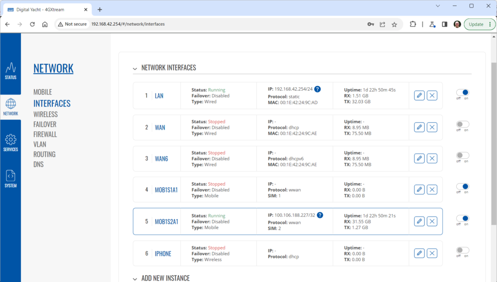
Click on the “Pencil” Edit icon for the SIM slot the EE SIM is inserted in – MOB1S2A1 in the example above.
Now you need to set Auto APN to OFF and enter the following details in the boxes that appear. Also make sure that PDP Type is set to IPv4 Only and not IPv4/IPv6 which is the default…
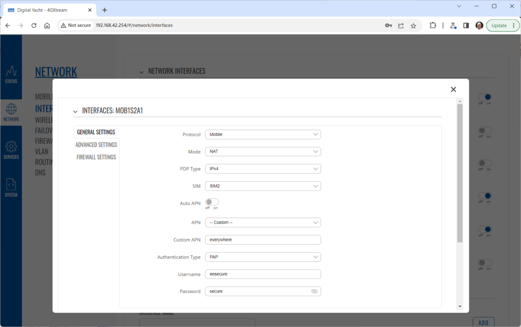
Once all of the settings are correctly entered, scroll to the bottom of the page and click the “SAVE & APPLY” button. Give the unit 20-30 seconds to apply the settings and reboot the modem and then you should see the DATA CONNECTION change to Connected and you will be online.
Connecting other Marine Electronic Equipment to our 4G Products
Many products from leading marine electronics manufacturers now feature a wired and/or wireless network interface. In some larger systems such as those from Navico/Garmin/Raymarine/Furuno, the MFDs, radar scanners, cameras and sonar systems will all be networked together via Ethernet cables. When one of our 4G Products is used as the central wireless router for internet connectivity, some customers have been confused as to whether they can join all of the devices together on one common network.
In general, unless indicated differently by the MFD manufacturer, it is best to leave the manufacturer’s wired Ethernet network, just for connecting the manufacturer’s equipment together and if you want to provide the system with an internet connection, to do this by connecting the master MFD wirelessly to our 4GXtream.
This will result in having two wired Ethernet networks on the boat, one for the navigation equipment and the other for internet access and normal IT type networking, but it will result in the most reliable operation of the two networks.
Most MFD manufacturers do not want customers to open up their Ethernet network to either a conventional LAN or WAN environment that they have no control over. Unknown network devices, levels of network data and protocols, can create interoperability issues that the manufacturer has never tested for, potentially having a serious, negative effect on the operation of their equipment.
The MFD’s wireless interface will be on a separate subnet and “locked down” so that it just does what they need it to do and no more. When you tell the wireless interface to join another wireless network in STATION (STA) mode, rather than its default ACCESS POINT (AP) mode, it will get an IP Address for the wireless interface from the 4GXtream and be able to go online for updates, weather data, etc.
4GXtream Power Consumption
The following power consumption figures are applicable to our 4GXtream. Power consumption does vary significantly, depending upon the amount of mobile data being transferred and how much wired/wireless network activity is taking place.
Below are the average consumption figures for 12v and 24v systems…
Minimum – Powered up but no mobile or network data transfer = 3.75W
Normal – Powered up with a couple of network devices doing light internet access = 4W
Maximum – Powered up with multiple network devices doing heavy internet access = 10W
How to connect 4G/5G Xtream to a WiFi hotspot?
Advanced Diagnostic Tests for our 4G/5G Products
In some situations, our 4G Products can appear to be connected to the internet, but due to other external conditions such as AV Software, ISP issues or local network settings, you cannot access websites from your browser. If this happens, there are some additional tests and checks that can be carried out.
Go to SYSTEM>ADMINITSTRATION>TROUBLESHOOT and do the following tests….
PING TEST
Enter an IP address of 1.1.1.1 and click the PERFORM button. This sends a series of data packets directly to a public website (Cloudflare) which then sends them back to your 4G Product over the Mobile network. The results are shown in the box below and if all of the packets are received, then the connection is good and it might be a DNS issue – continue to the Trace Route Test.
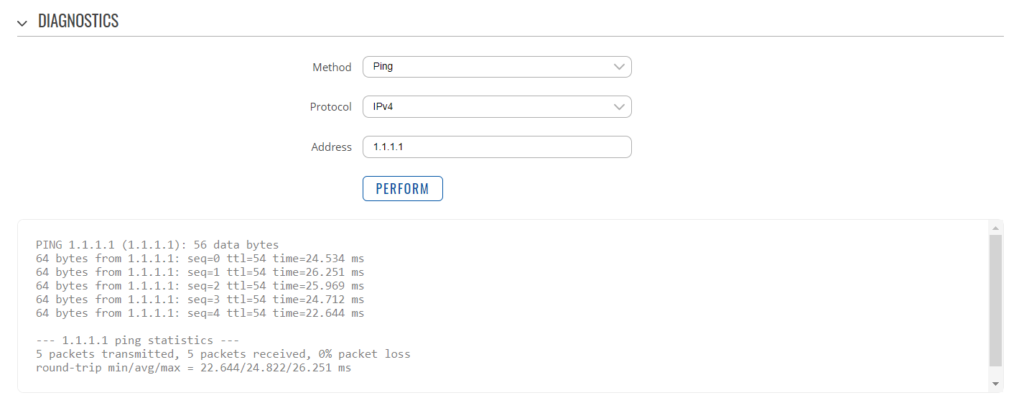
Traceroute Test
Change the method to Traceroute and the address to www.google.com and click the PERFORM button again, you should see the following info in the box that traces, the route through the internet to the Google web server. If the test fails and the Google site is not reached, then you may have a DNS setting issue on your wireless device. Try setting it to use a fixed DNS server address of 8.8.8.8 which is the Google public DNS server.
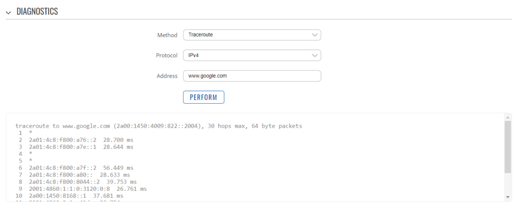
Check SMS Messages
Sometimes, it can be an issue with your mobile network operator account that is stopping the internet access. Please check if you have received any notification SMS messages from the Mobile Operator that might explain why we are connected but not getting a good internet connection? To do this, go to SERVICES>MOBILE UTILITIES>MESSAGES and you should see any SMS messages that the Mobilke operator have sent you…
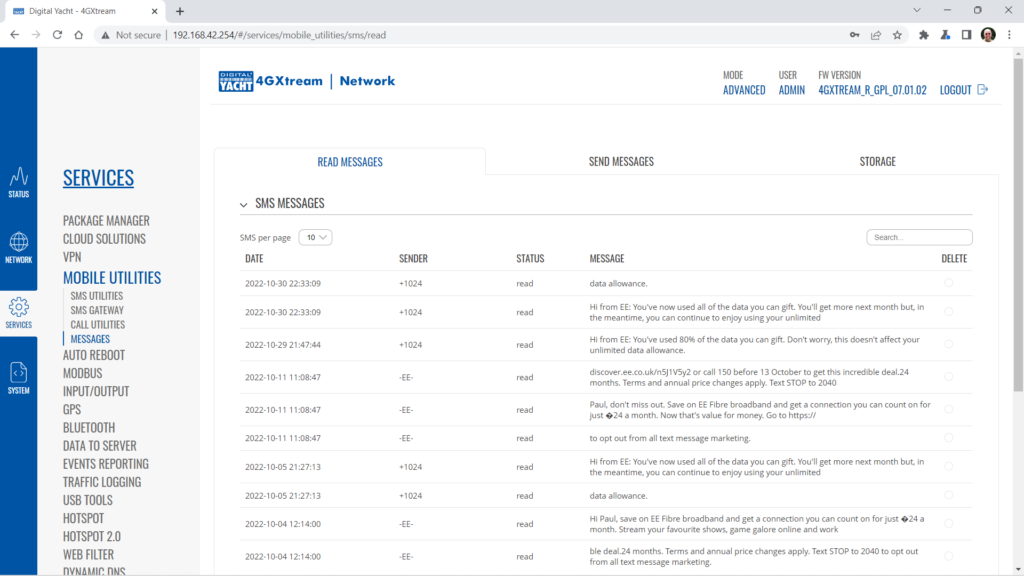
Finally, some anti-virus, VPN or network security software has been known to block mobile internet connections, particularly common on business computers. Try temporarily turning off any anti-virus, VPN or network security software and see if that fixes the problem. If it does, make sure that your new 4G Product is in the list of “Safe Networks” in your anti-virus/security software.
Generating Diagnostic Information on our 4G/5G Products
Our 4G Products are used globally on lots of different networks and occasionally, due to incorrect APN settings or SIM card issues, a unit will not correctly register on the mobile network and no internet connections will be available.
In this situation, please start by checking the SIM card, as per this article that we published on our blog…
https://digitalyacht.net/2022/08/12/getting-correct-sim-cards-4g-products/
If that does not resolve the situation, then in order to assist you our support team will need the following screen shots and information…
- A screen shot of the STATUS>OVERVIEW page – first page that you see when you log in to the web interface.
- A screen shot of the STATUS>NETWORK page which lists all of the mobile network info.
- The unit’s troubleshooting file, go to SYSTEM>ADMINISTRATION and then go to the Troubleshoot tab. Scroll down the page and click the Troubleshoot File DOWNLOAD button. Send us the GZIP file that it downloads to your device.
How to transmit the 4G / 5G Xtream’s GPS data on an NMEA 2000 Network
One of the lesser known facts about our 4GXtream, is that it has a built-in GPS receiver and is supplied with a passive GPS antenna. This is primarily for position logging or for enabling a geo-fence alarm function. However, this GPS data can also be transmitted out on the NMEA 2000 network.
Assuming that the 4GXtream GPS antenna is connected, it is getting a good position fix and the NMEA 2000 cable is connected to a fully powered up and operational NMEA 2000 network, the notes below will configure the 4GXtream to become an NMEA 2000 GPS position source.
From a device that is wirelessly connected to the 4GXtream, open a browser and bring up the web interface at http://192.168.1.1, and then login to the 4GXtream web interface. If the 4GXtream is in BASIC mode, click on the word BASIC and you will be asked if you want to go in to ADVANCED mode, confirm that you do. Now go to SERVICES>GPS>GENERAL and make sure the GPS is enabled…
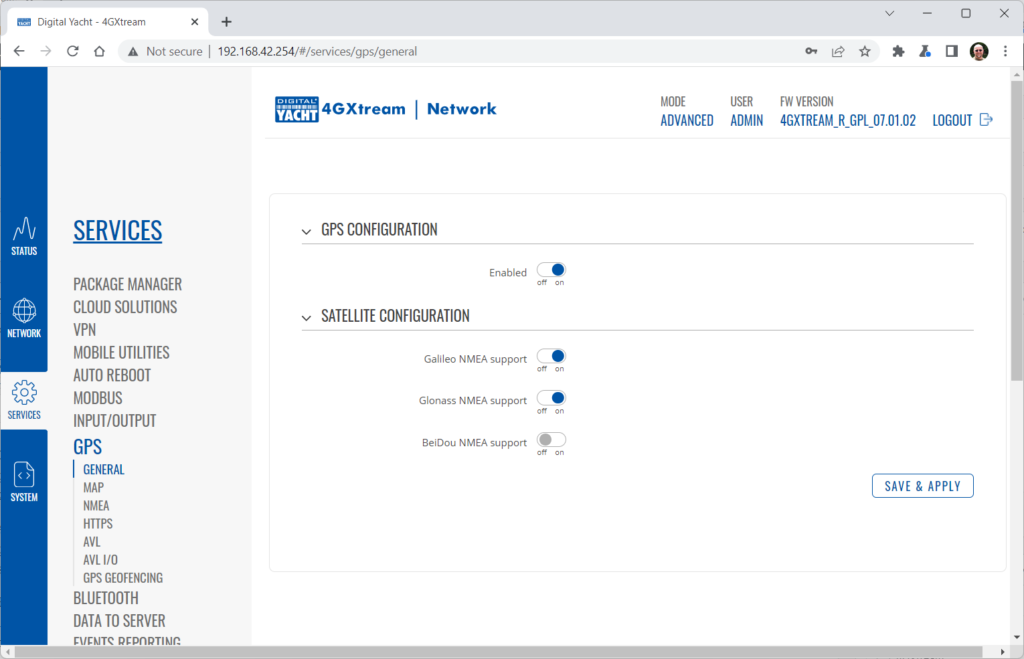
Now go to the SERVICES>GPS>MAP and make sure that your current position is being shown correctly on the map…
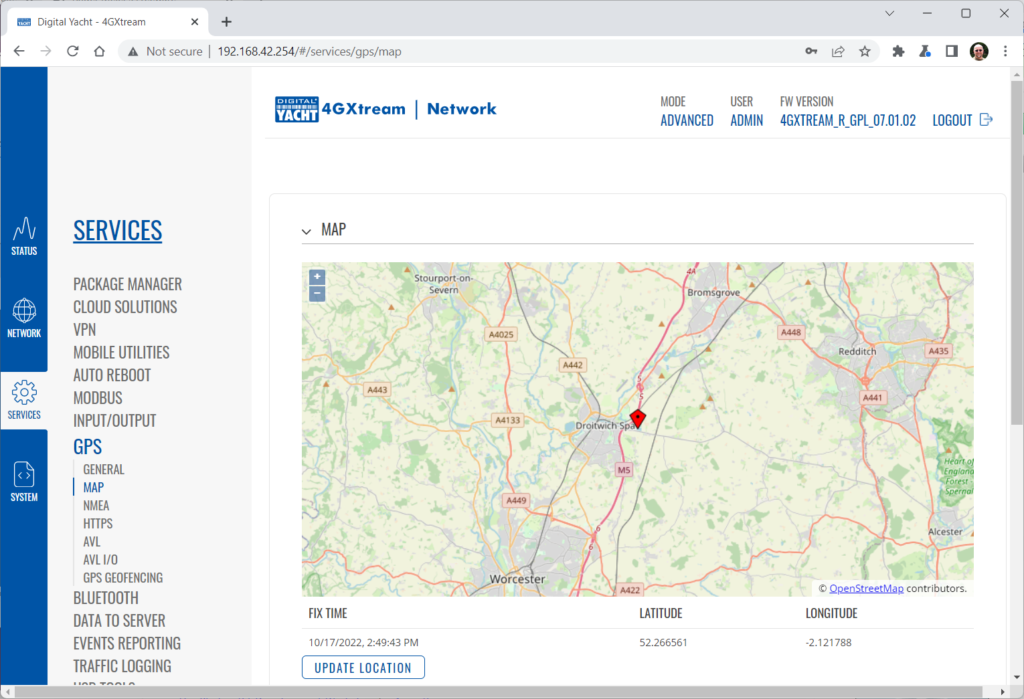
Now we need to send the GPS data to the USB port which is connected to the 4GXtream’s NMEA 2000 gateway. This is done by creating an internal “loopback” TCP connection and then sending the output to the USB port as a Serial data stream.
First go to SERVICES>GPS>NMEA and configure the NMEA Forwarding settings as shown…
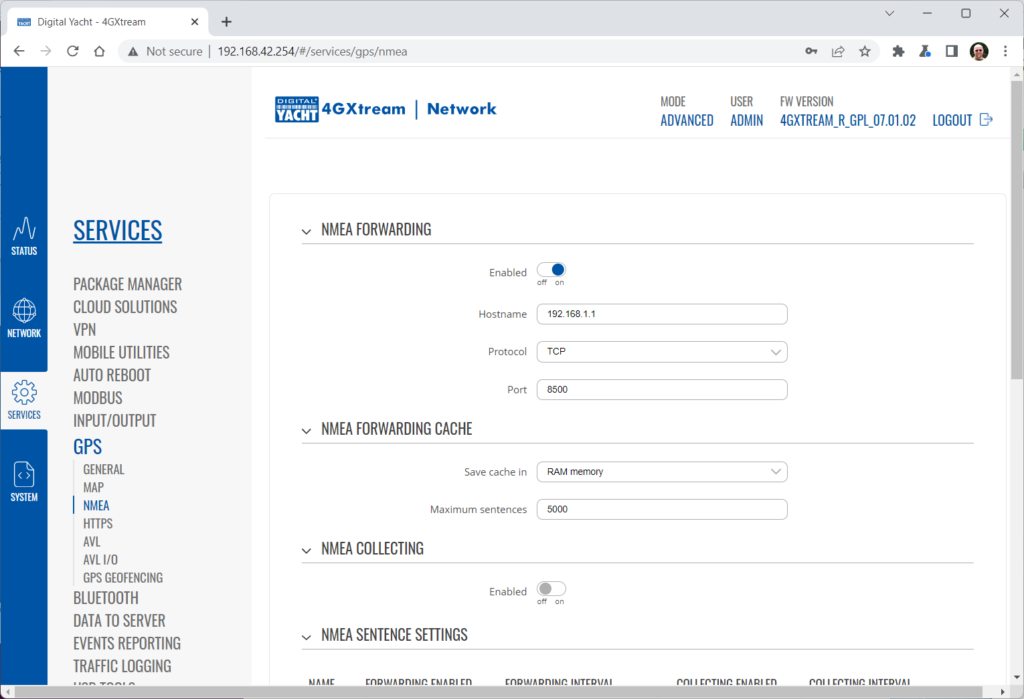
Scroll further down and in the NMEA Sentences Settings, turn on the GPGGA and GPRMC sentences with an interval of 1sec…
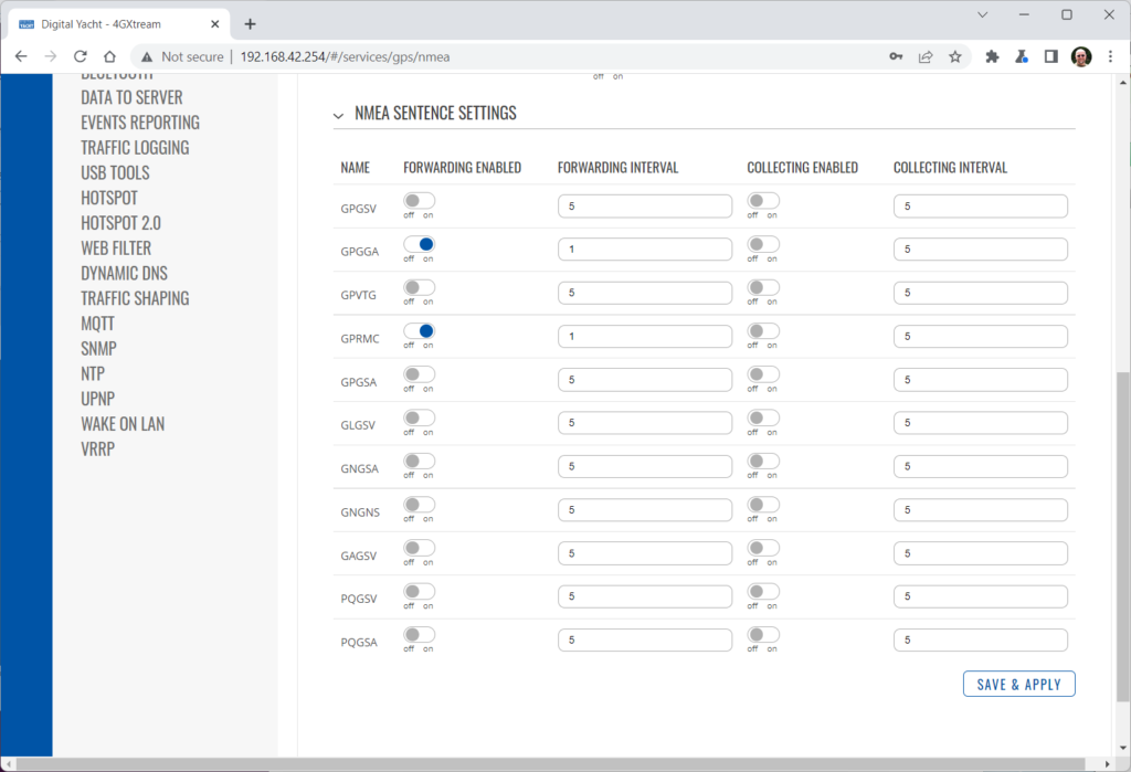
Click SAVE & APPLY and then move on to the SERVICES>USB TOOLS>USB TO SERIAL settings and set them as follows, noting that the ID has already been automatically set and will be different to the value below (DO NOT CHANGE IT)…
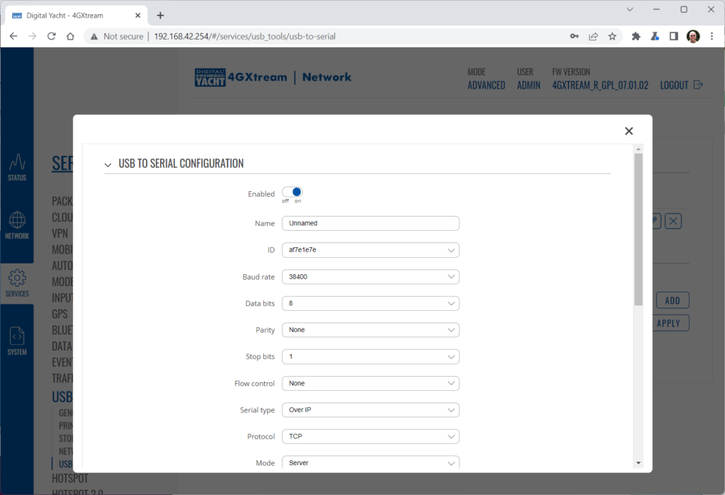
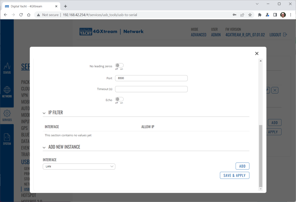
Click the SAVE & APPLY button and now your GPS data will be sent to the NMEA 2000 gateway and on to the NMEA 2000 network. If you have other GPS Position sources on the NMEA 2000 network you will need to make sure that you select the 4GXtream as the preferred position source when you wish to use it – it will appear on the NMEA 2000 as a Digital Yacht N2Net NMEA2000 Serial Gateway.
4G Xtream Factory Reset Procedure
With the unit fully powered up i.e. connect power and wait >1 minute for it to boot up, using the supplied SIM removal clip or some other blunt pointed object, gently press and hold the small Reset Switch on the front face of the unit, for at least 5 seconds as detailed below for the Factory Reset function….
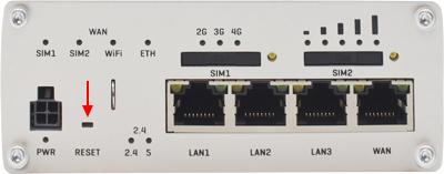
The reset button has two functions:
- Reboot the device. If the reset button is pressed for up to 4 seconds, the device will reboot. Start of the reboot will be indicated by the flashing of all 5 signal strength LEDs together with the green connection status LED.
- Factory reset. If the reset button is pressed for at least 5 seconds (by default), the device will perform a factory reset and reboot. Signal strength LEDs indicate the elapsed time while holding the reset button. When all 5 LEDs light up, it indicates that 5 seconds have passed and the reset button can be released. Start of the factory reset will be indicated by flashing of all 5 signal strength LEDs 5 together with a red connection status LED.
After the unit has been reset, all of the settings will be back to as they were when it left our factory.
The 4GXtream is a powerful device with lots of functionality and unless you are an experienced IT Engineer, then the only configuration changes that we would recommend are…
- Manually set the APN settings if the automatic default settings have not successfully connected the 4GXtream to the internet
- Set the Wireless Network Name and Wireless Password to values of your choosing so that only the people you want to connect to the 4GXtream can connect to it
All of this is covered in our latest User Manual;
How to tell what firmware your 4GConnect or 4GXtream has?
The firmware version is normally displayed in the top right hand section of any of the web pages….example below of the original 4G Connect “Black & White” web interface and the latest “Blue & White” web interface…
The 4G Xtream only has a “Blue & White” web interface.
VPN on our 4G Products
Setting up remote access to any network that is operating on a mobile LTE (3G/4G) network is never easy, even for experienced IT engineers. Unfortunately, Digital Yacht just do not have the resources or depth of knowledge to support our customers in doing this on an individual basis.
When your remote network is “hidden” inside a mobile network that abstracts all external connections to the internet, the only way to create a VPN is for the 4GConnect/4GXtream to initiate a connection to your VPN server or shared cloud server that does the data routing for you.
Our 4GConnect is based on OpenWRT, which supports two different VPN services; OpenVPN and ZeroTier, plus a couple of tunnelling protocols that could be used as an alternative to VPN. If you do not have the services of an experienced IT engineer to help with setting up a solution, then I would look for examples of connecting to a remote OpenWRT network over LTE using VPN services.
Here is a link to the OpenVPN documentation on the OpenWRT site and it covers using either a Client or Server setup. Hopefully with this information you will be able to find the relevant settings in our 4G products to setup your VPN.
https://openwrt.org/docs/guide-user/services/vpn/openvpn/start
I want to set up my AT&T Sim card
If you have an AT&T Sim Card, then you need to be in “Advanced” Mode, click the word “Basic” in the web page header and then go to Network>Mobile and set the Service Mode to “4G (LTE) Only” and then click the “Save+Apply” button at the bottom of the page….
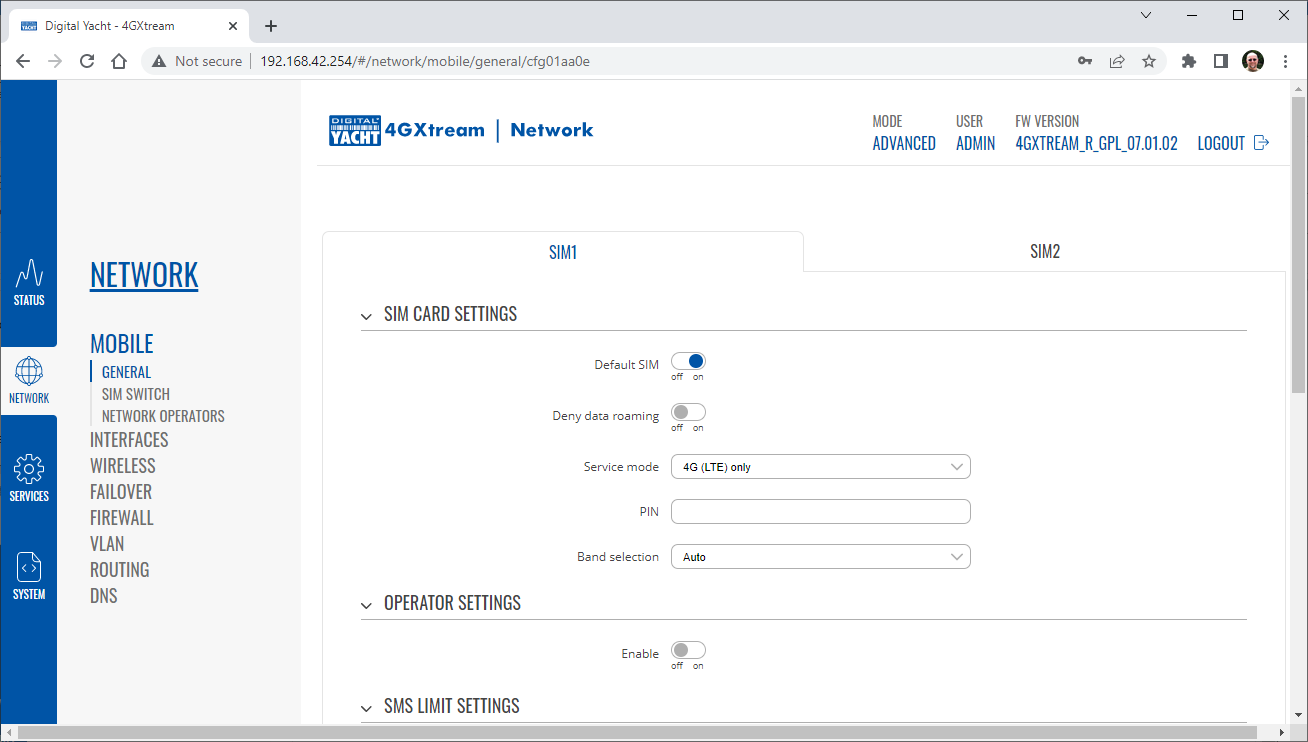
After the new settings have been applied, go to Network>Interfaces and then click on the “Pencil” Edit button of either MOB1S1A1 (SIM1) or MOB1S2A1 (SIM2) depending upon which SIM slot the AT&T SIM is in….
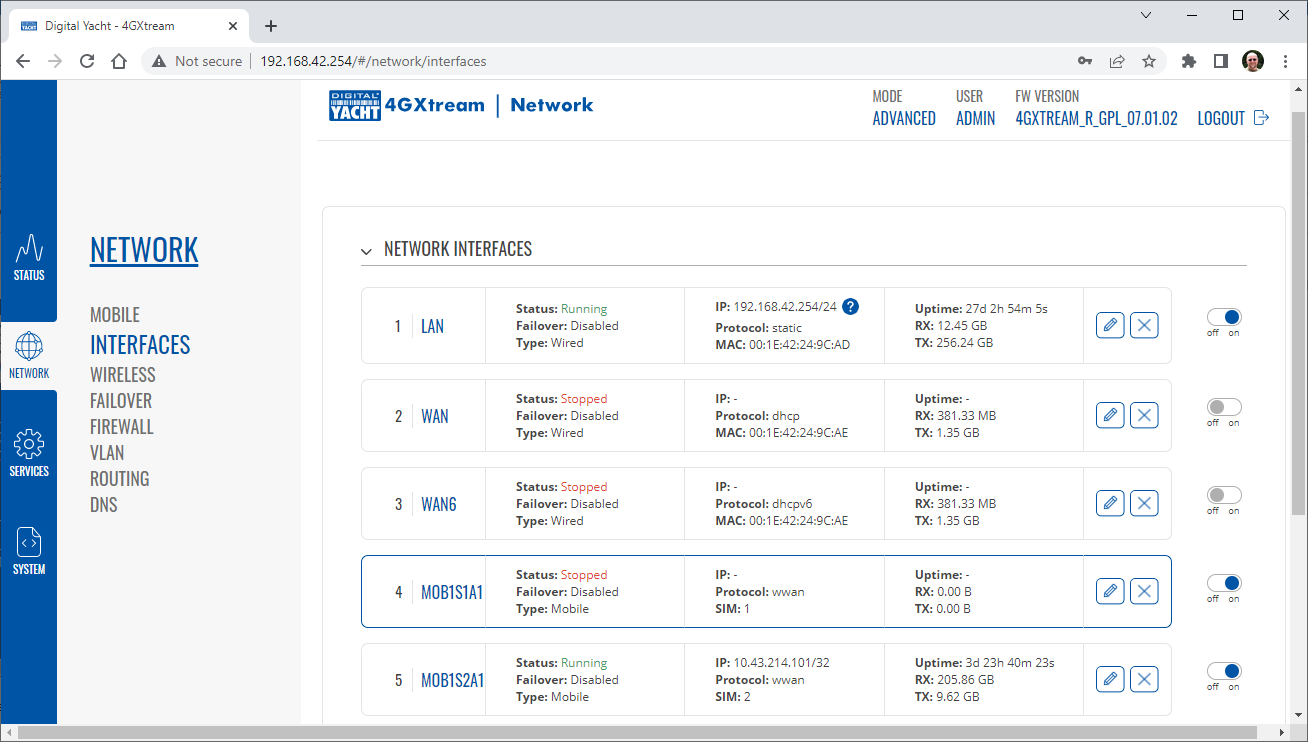
In the Pop-Up settings window, turn off the Auto APN switch and some new boxes will appear. Select “Custom” from the drop down APN list and then type “Broadband” in the Customer APN box exactly as written with a capital B and then click the “Save+Apply” button at the bottom of the page…
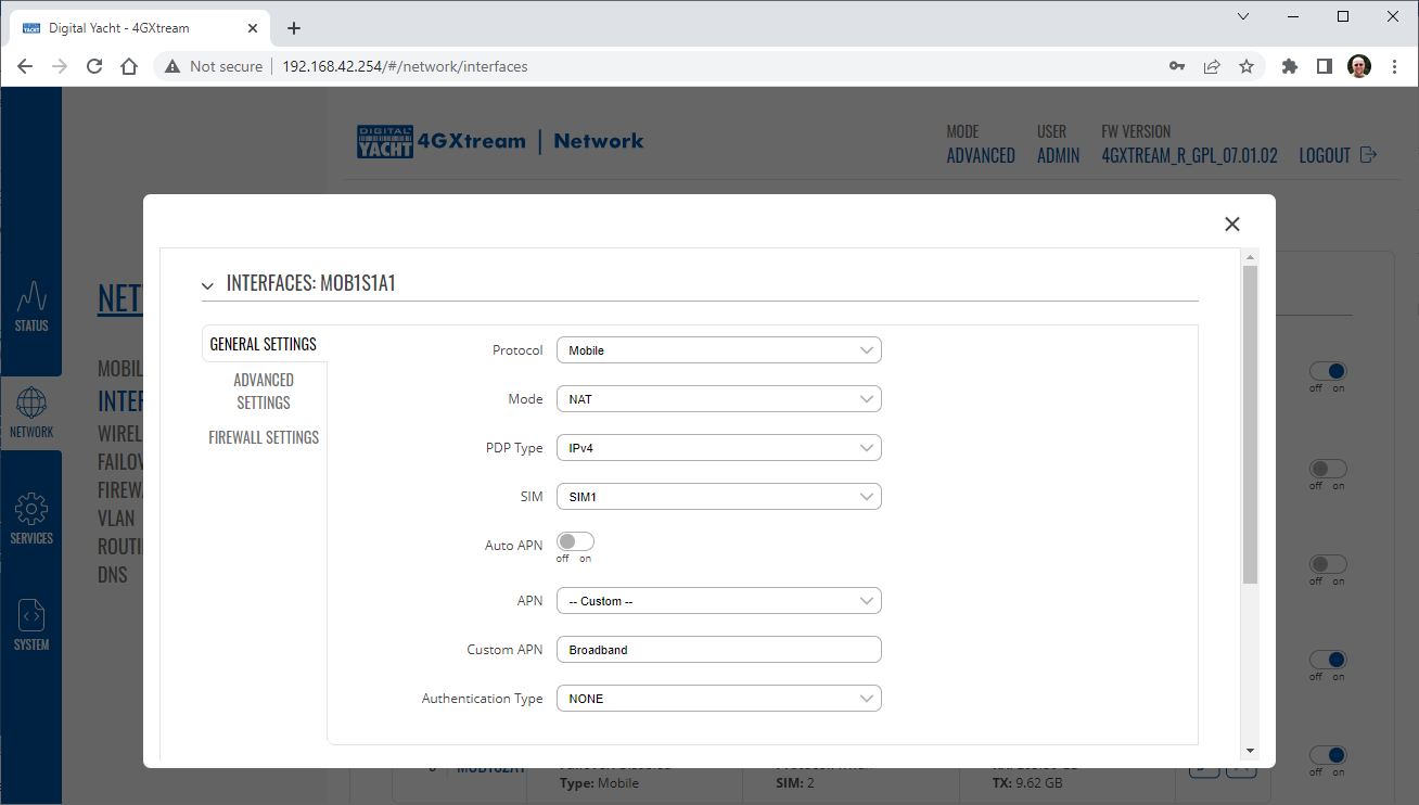
After the settings have been applied, go to Status>Overview and check in the Modem panel that you are connected.
Now try going to another website to check you have internet.
Configuring our 4GXtream to work with RAW NMEA 2000 PGN’s
So out of the box our 4GXtream units work in High Speed Gateway Mode and will convert NMEA 2000 data to NMEA 0183, which for users who just want basic navigation data, will be enough. For advanced users that want software such as Expedition to receive all of the NMEA 2000 data in RAW Mode, then you will need to do the following….
Make sure that your 4G Xtream has the latest firmware. When you update your firmware unit, using the System>Firmware menu option, please remember to turn off the “Keep Settings” switch.
1) With the 4GXtream powered down and disconnected from the NMEA 2000 network, unscrew all of the top screws (from both end caps). Then unscrew the two bottom screws in the Antenna End Cap and gently move this end cap way from the enclosure as far as possible without putting undue tension on the small coax cables inside.
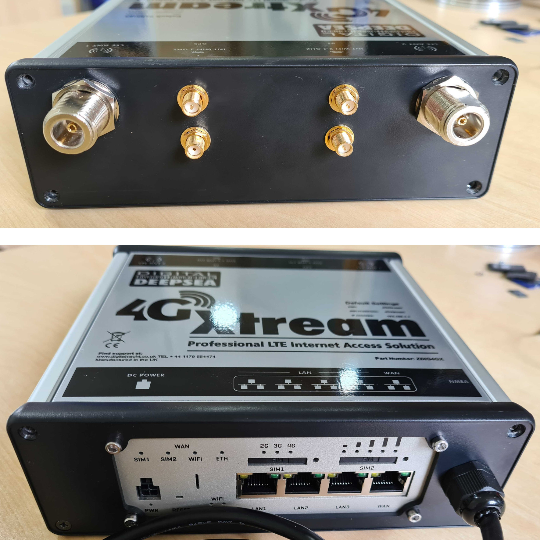
2) It should now be possible to gently slide out the top of the aluminium enclosure (top face with product label on).
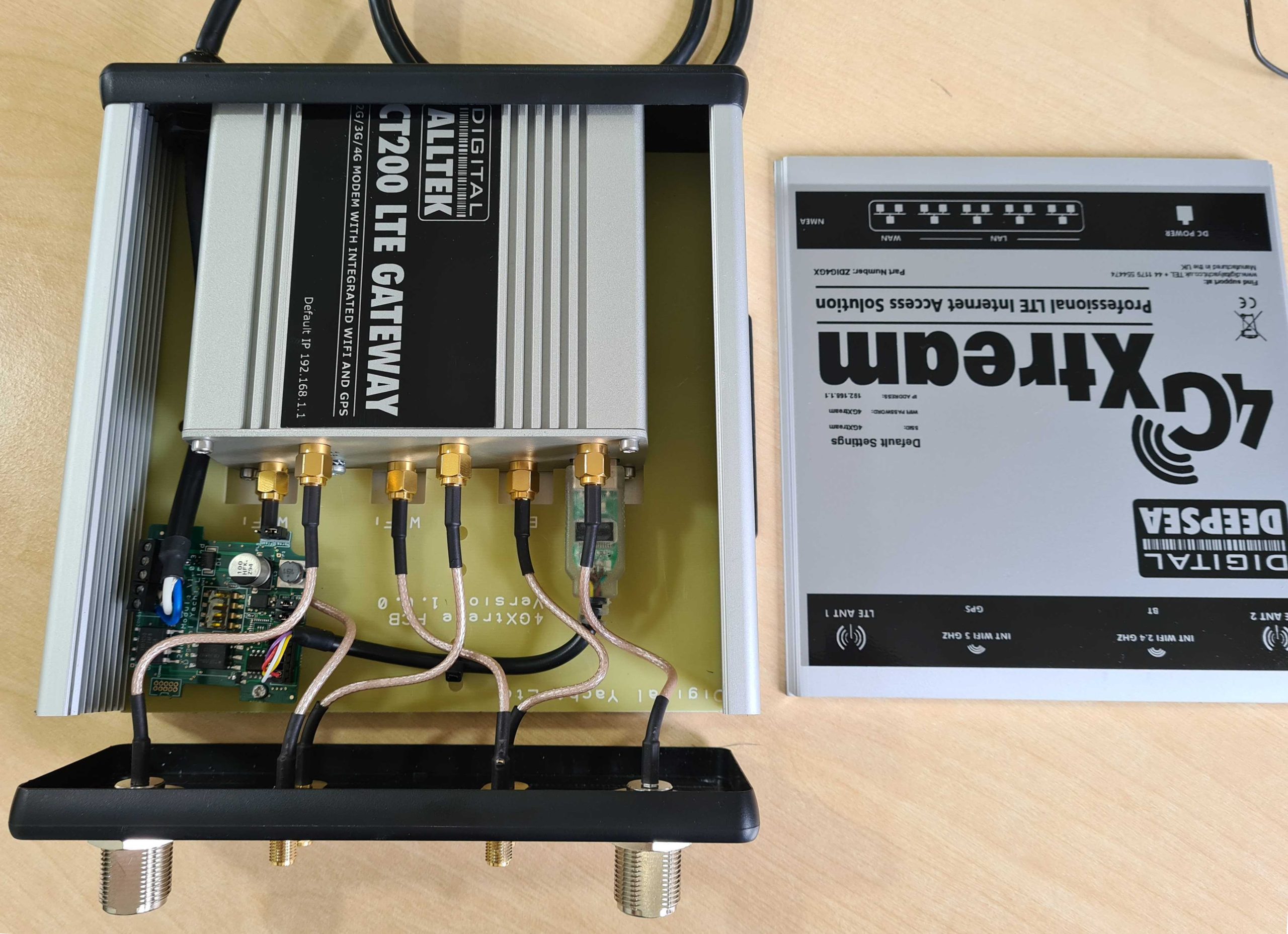
3) With the top of the enclosure removed, you will see the small gateway PCB which has 4x DIP Switches in the middle. All of the switches except switch 4 will be in the OFF position (default positions).
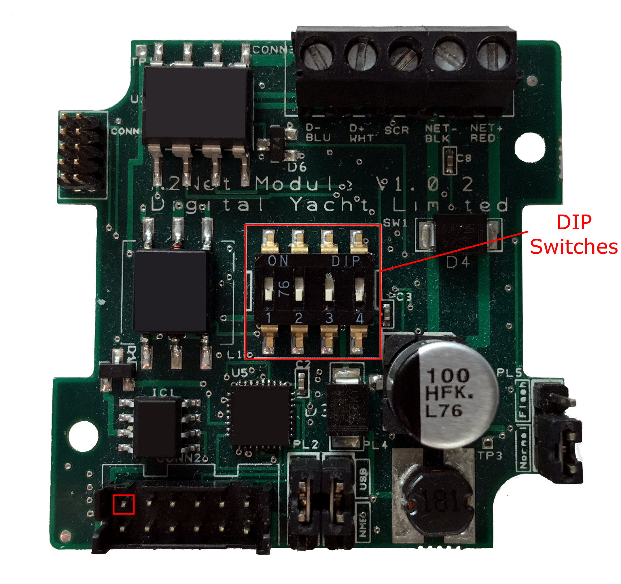
4) Using a small screwdriver or any other fine tipped tool, very gently push switches 1, 2 and 3 in to the ON position so that all switches are in the opposite position to the image above.
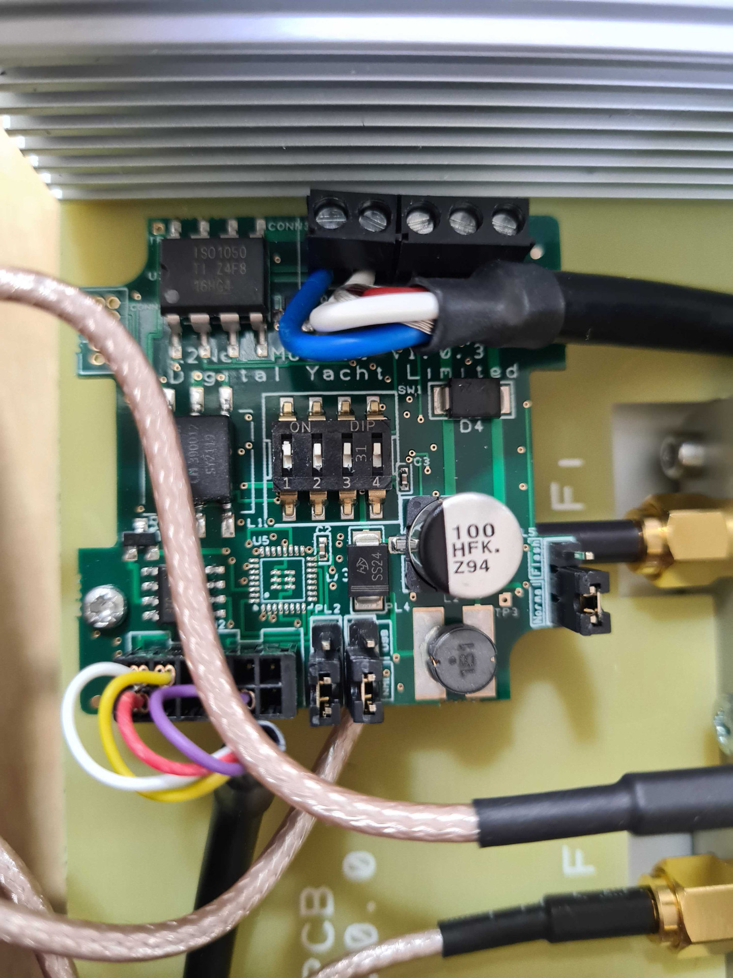
5) Re-assemble the 4GXtream, by reversing the steps above and once back together, connect the NMEA 2000 cable to your NMEA 2000 network and turn on the 12/24v Power to the 4GXtream.
6) After 45-60secs, the 4GXtream wireless network should appear. Connect your wireless device to the 4GXtream wireless network and then open a browser and go to http://4gxtream or http://192.168.1.1
7) Login to the 4GXtream web interface using Username = admin and Password = 4GXtream and go to Services>USB Tools>USB to Serial
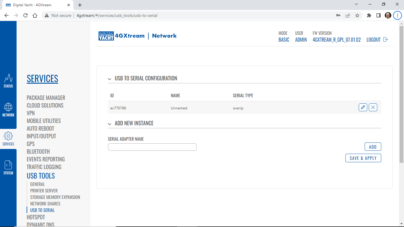
8) Click on the “Pencil” Icon to edit the USB to Serial settings and then simply change the Baud Rate setting to 230400 and click the SAVE+APPLY button at the bottom of the page.
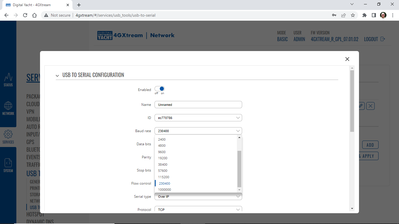
9) Now you can go to a terminal program like Tera Term and setup a Telnet (TCP) client connection to the 4GXtream (192.168.1.1) on Port 2000. You should see a TCP connection open and the HeartBeat (Network Status Message) appear every second from the iKonvert…
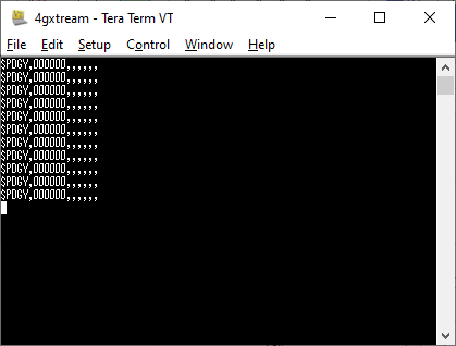
10) If you want to see the RAW NMEA 2000 data, then you can initialise the iKonvert by sending the following command, must remember to set the terminal program to send <CR><LF> as the End of Line (EOL) command…
$PDGY,N2NET_INIT,ALL
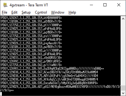
General Information on 4G/5G Products (Configuration, updates, SIM cards)
If you have any issue with your 4G product then It is always worth updating your 4G Product to the latest version. This article, although written about the AT&T update, is still applicable for any unit.
Updating 4G Firmware
Please note that older 4GConnect units must do a two stage update to go from the first “Black and White” web interface version, to the latest “Blue and White” web interface version. The V01.14.05 is a special intermediate version (last of the “Black and White” generation) that must be loaded first, in order to make the jump to the new V07.02.08 firmware.
https://digitalyacht.net/2022/03/04/important-update-4g-products/
Configuring 4G Product
Here is the link to the very useful video on configuring our 4G Products – shows the latest “Blue and White” web interface…
https://digitalyacht.net/2022/03/04/important-update-4g-products/
Getting the correct SIM card
Here is the most recent article on SIM cards. If the customer is getting a good mobile phone signal on the 4G Product and the SIM card is being read, the network operator is recognised, etc. then it could be a SIM issue and this article explains what needs to be checked…
https://digitalyacht.net/2022/08/12/getting-correct-sim-cards-4g-products/
4G/5G Products – Reboot in case of Mobile Network Disconnection
This procedure is good for boats that are regularly going a long way offshore outside of mobile network range, such as fishing boats, blue water yachts, etc. Basically, our 4G Products can sometimes not reconnect properly when they come back in to mobile range and this feature makes the 4G Product keep checking if it is online and if it is not it will reboot the modem.
Ping Reboot Configuration
To enable the “Ping Reboot” feature, go to SERVICES>AUTO REBOOT and you will see a similar page to the one below…
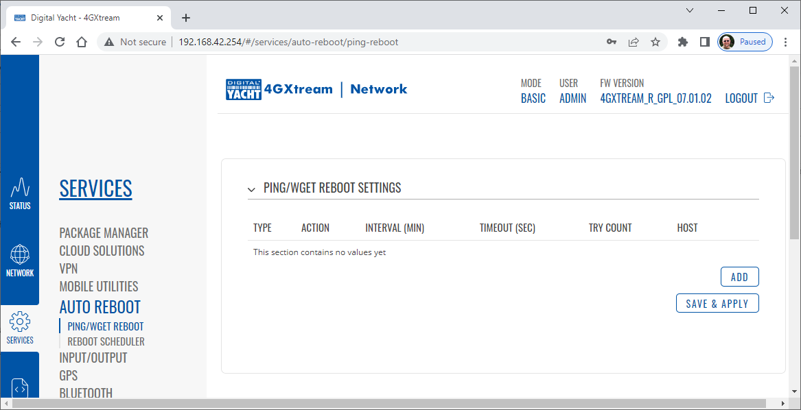
Now click the ADD button and I would suggest you use the same settings as shown below, which are the ones I have used in all of our testing. Every 2 minutes, 4GXtream will ping 8.8.8.8 which is the Google public DNS server and is always online.
If it does not receive a reply within 5 seconds, it retries two more times and if there is still no reply it restarts the 4G Modem.
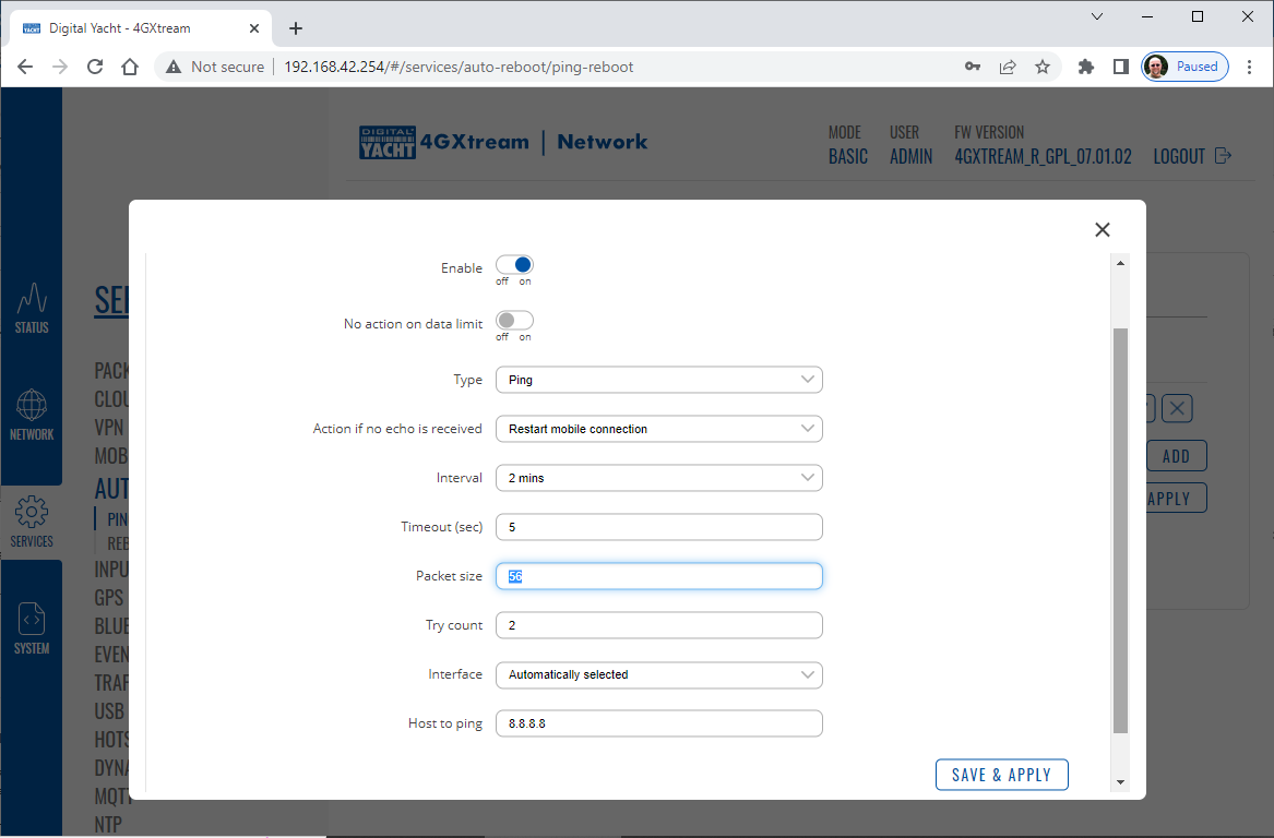
Click the “SAVE & APPLY” button and after the settings are stored, you should not have to manually reboot the 4GXtream again.
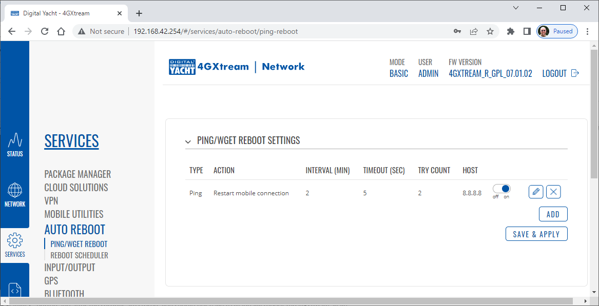
How to configure our 4G products?
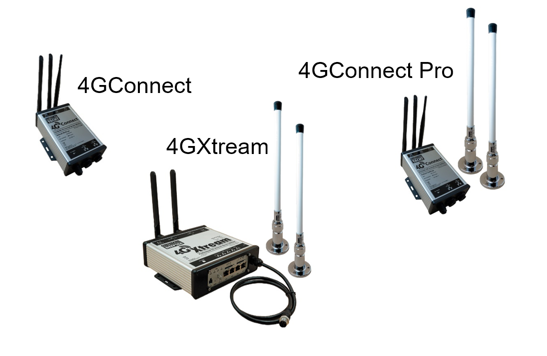
Since COVID forced many of us to start working remotely, we are seeing an ever increasing demand for our 4G Products. Once installed and working, these products are extremely reliable, but with so many mobile network operators around the world, initial setup can be confusing. To help our customers get up and running as quickly as possible, we have created a new video on configuring our 4G Products.
This video is filmed using one of our 4GXtream products, but is equally applicable for our 4GConnect and 4GConnect Pro products, particularly if you have updated to the latest V07.01.02 firmware as detailed in a previous post “Important Update for our 4G Products”. This update adds the same, new “Blue and White” web interface to our 4GConnect, as our 4GXtream has and will be the interface that all future videos and technical documents will be based on.
How to override the Auto-APN Settings?
Our 4GXtream router but also the latest 4G Connect version have a new “Auto-APN” feature that reads the SIM details and selects the correct APN settings for the SIM’s mobile network. APN stands for Access Point Name and are the settings your 4G product needs to pass to the network carrier; AT&T, Vodafone, T-Mobile, etc. in order for the carrier to allocate your 4G product an IP address and connect you to the right secure network.
On many networks the new “Auto-APN” feature works very well, but today we had a Vodafone customer contact us who could not get their 4GXtream to connect correctly. The solution was to manually override the APN settings, by following the procedure below.
- Go to the 4GXtream/4GConnect’s web interface at http://192.168.1.1 and login
- By default the 4GXtream or 4G Connect is in “Basic” mode and you need to click on the word Basic in the top right hand section of the web page, to enable “Advanced” mode.
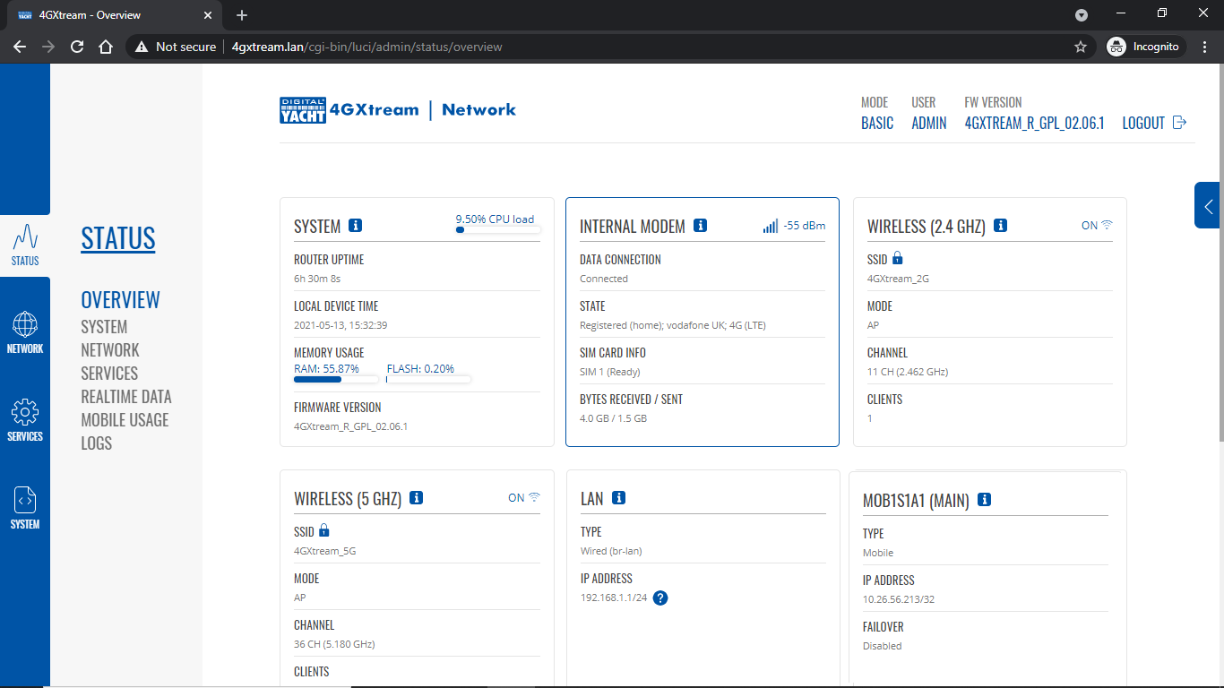
Now go to NETWORK>INTERFACES and click on the Edit button (pencil icon) of the SIM card interface you are using, SIM 1 in the example below.
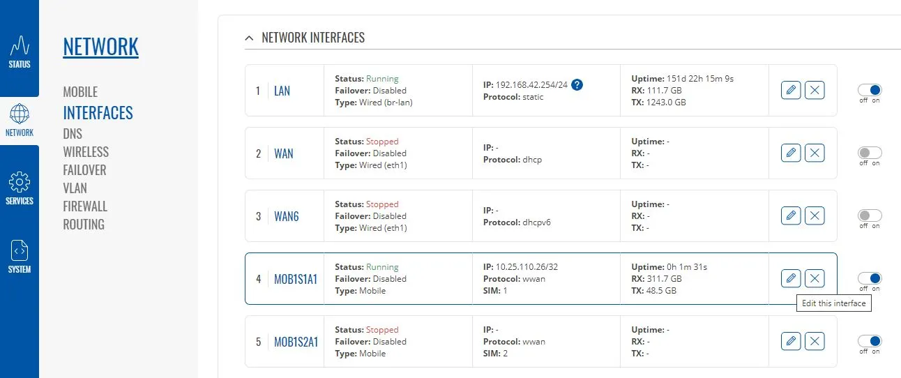
You can now edit the SIM settings to disable Auto-APN mode and add manual “Custom” APN settings, as shown below which are the correct settings for a Vodafone UK (contract) SIM. Once you have set the manual APN settings click the “Save & Apply” button and once the settings have been changed, go to the STATUS>OVERVIEW page to see if you now have a connection to the internet.
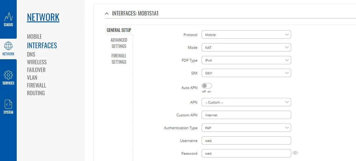
If your network carrier has not given you your APN settings, then this is a pretty good site to try and we would be really grateful if you could let us know if the Auto-APN settings work for you or what manual settings you had to use.
Getting the Correct SIM cards for our 4G Products
One of the most common problems, that the Digital Yacht support team help our 4G Product customers with, is SIM card issues. This little piece of plastic, with its integrated memory chip, containing a unique identifier, that allows your data usage to be tracked, causes a disproportionate amount of wasted time and effort, so we decided to publish a guide to avoid the pitfalls that we regular see.
Not all SIMs are created equal and with the majority aimed at mobile phone users, it is important that the SIM you use in our 4G Products meet the following criteria….
- It is a 4G SIM (not 5G)
- It is a Data Only SIM – designed for wireless routers and not mobile phones
- The SIM should not have a PIN number enabled or if it does, that you know what it is
- The SIM has not reached its Data Limit
- That the SIM is properly registered and enabled by the network operator
- If being used Internationally that the SIM has roaming enabled
Once you are confident that your SIM meets all of the above criteria, please insert it in to our 4G Product and using the web interface, go to STATUS>NETWORK where you should see a screen similar to the one below, minus the red annotations….
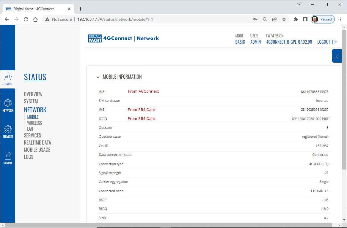
The key pieces of information to look for on this page are that the SIM Card State shows “Inserted”, which means that it has been read by our 4G Product. Then you should see the IMSI and ICCID numbers, which are stored on the SIM and used by the 4G Product to identify itself to the network operator.
- IMSI = International Mobile Subscriber Identity. This is a unique identifier that defines a subscriber in the wireless world, including the country and mobile network to which the subscriber belongs. It has the format MCC-MNC-MSIN. MCC = Mobile Country Code (e.g. 310 for USA); MNC = Mobile Network Code (e.g. 410 for AT&T), MSIN = sequential serial number. All signaling and messaging in GSM and UMTS networks uses the IMSI as the primary identifier of a subscriber.
- ICCID = Integrated Circuit Card ID. This is the identifier of the actual SIM card itself – i.e. an identifier for the SIM chip. It is possible to change the information contained on a SIM (including the IMSI), but the identify of the SIM itself remains the same.
The IMEI number is unique to the 4G Product’s modem and will always be displayed, even if the SIM is not inserted…
- IMEI is short for International Mobile Equipment Identity and is a unique number given to every single mobile phone, typically found behind the battery. IMEI numbers of cellular phones connected to a GSM network are stored in a database (EIR – Equipment Identity Register) containing all valid mobile phone equipment. When a phone is reported stolen or is not type approved, the number is marked invalid.
Other key information on this page are the Operator and Operator State. The image above was using a SIM from UK operator 3 which was a fully registered, had plenty of Data and had established a data connection.
Assuming that you have followed this guide and selected the right SIM card, then there is one last hurdle to overcome, making sure that our 4G Product is using the right APN settings for the SIM’s network operator. The Access Point Name (APN) settings, vary from network operator to network operator, and with the latest firmware updates, our 4G Products will automatically try and set these from a database of popular APN settings. However, for some networks, it is still necessary to manually enter the APN settings, please see our configuration video for more details.
Once you have everything working, there should be no need to make any further changes to the settings, but occasionally the connection will fail. This can be for a number of reasons, but more often than not, particularly if you are using a Pay As You Go type SIM or you are using International Roaming, it will be a network operator issue and you should check that you have not received an SMS notification from the operator.
To do this, go to the SERVICES>MOBILE UTILITIES>MESSAGES screen where all of the received SMS messages are displayed…
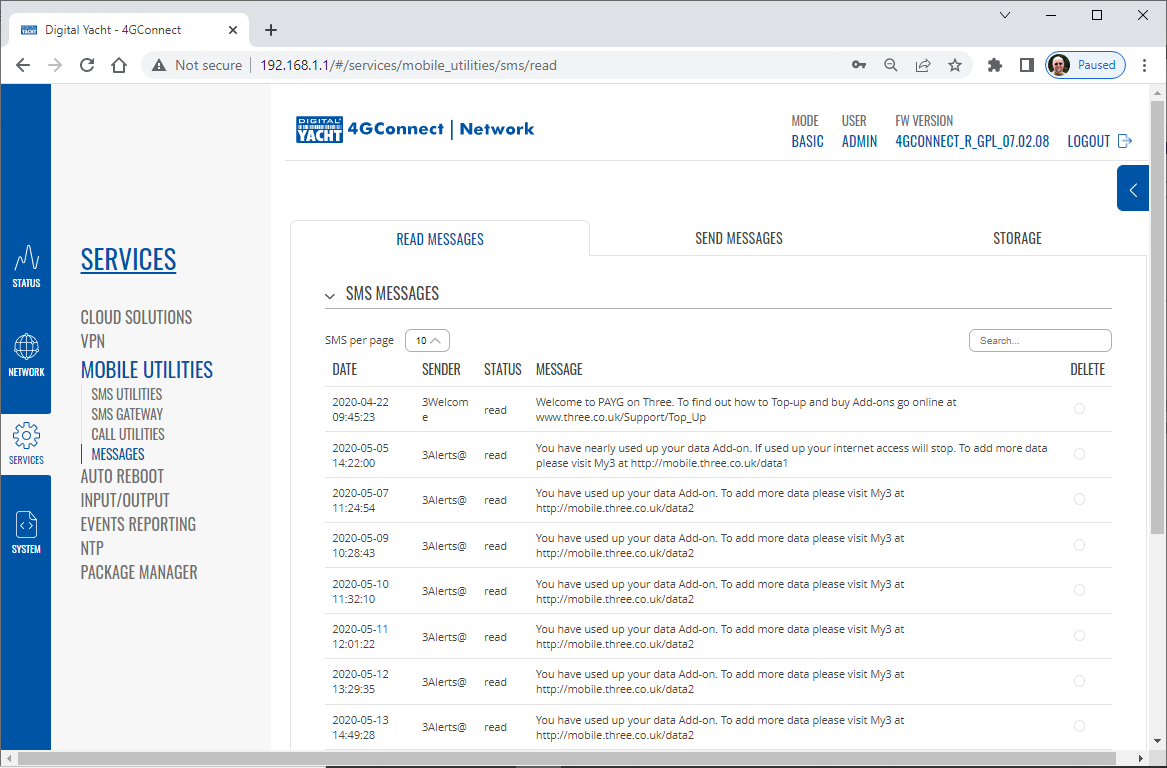
Make sure there are no “Data Limit” or “Roaming” related messages that might account for your loss of connectivity and if you are still having problems after rebooting the modem, which you can do at the bottom of the STATUS>NETWORK page, please contact your network operator to check the status of your SIM account.
Using WL510 with 4GXtream
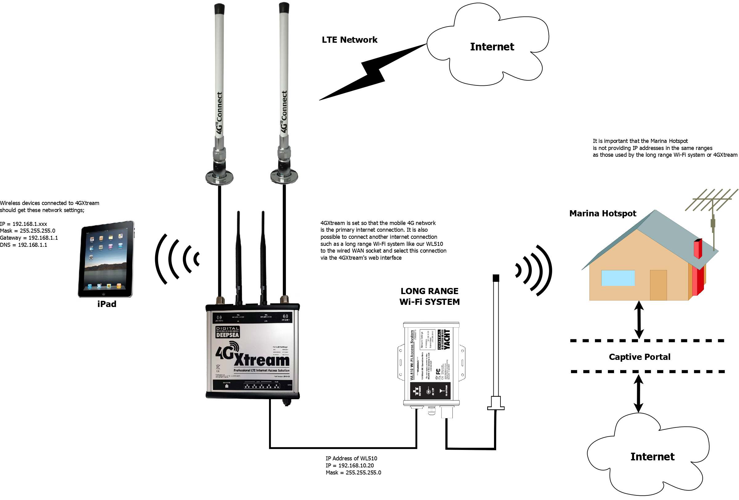
To decide whether to use the Mobile 4G connection or the WL510 long range wireless connection, you will need to go in to the 4GXtream web interface and click on the Network>WAN menu option….which will display the page below.
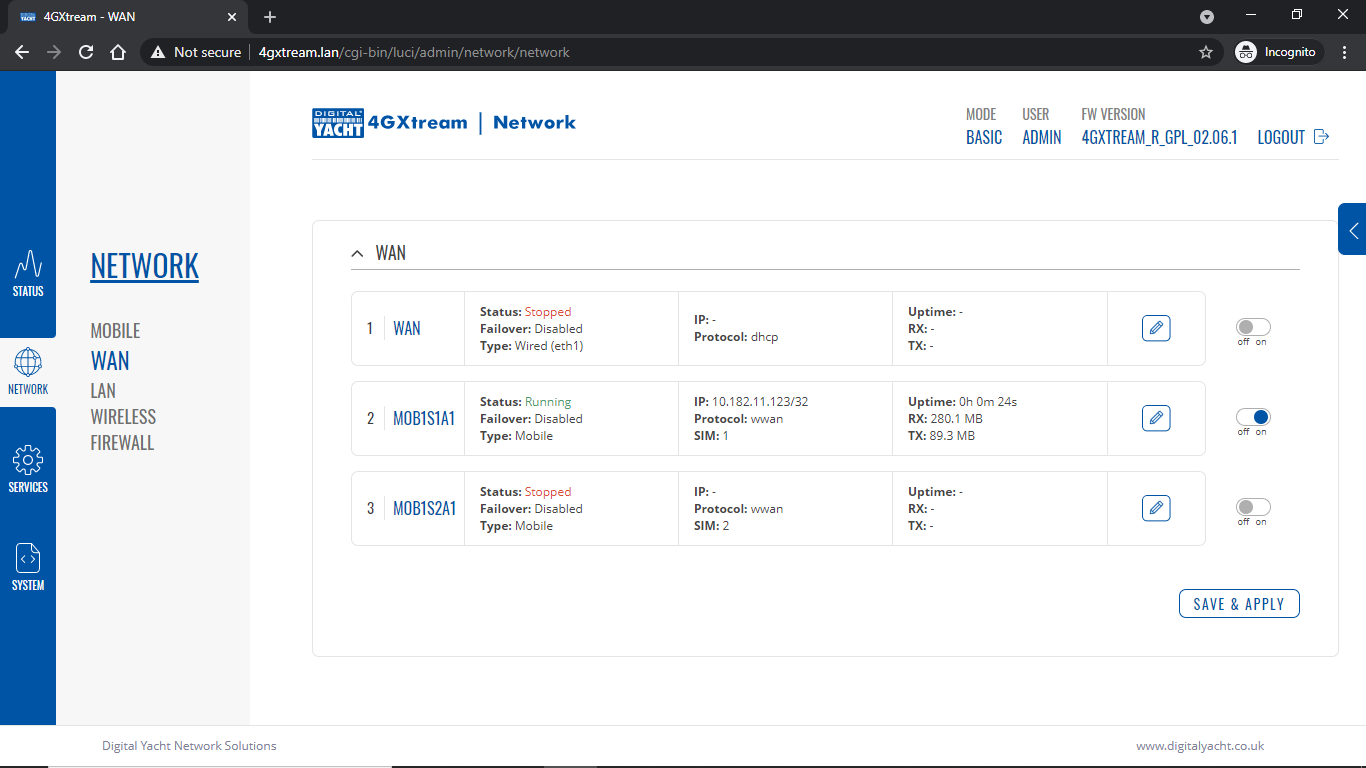
You can use the switches at the end of each line to select whether you want to connect to the internet via Mobile 4G or via the WL510 Wi-Fi on the wired WAN interface. In the screen shot above, taken from my boat’s 4GXtream, I do not have an WL510 wireless booster connected to the Wired WAN interface, so it does not show any information about it but on your unit, with the WL510 connected, there should always be an 192.168.10.xxx IP address and uptime values.
Just click Save and Apply after making your selection.
Is the SIM or Network Operator causing the problem?
If the unit has been working and suddenly stops or you have followed the steps above and everything appears to be OK but you still do not have a connection to the internet, then the fault is likely to be with the SIM or network operator. Could any of the following factors be applicable?
- The SIM is a Pay as You Go type and the credit has expired?
- The SIM is a normal mobile phone SIM and not a Data Only SIM which some network operators insist must be used in wireless router type systems?
- The SIM is a monthly contract SIM but has a data limit that you have exceeded?
- You are using the SIM in another country but the network operator has not enabled roaming?
- The SIM is not properly registered?
The only option in this situation is to contact the network operator, which can be a convoluted exercise, but we have seen this situation many times and if you can get through to the right person and tell them the exact nature of the problem, then it can be resolved.
Are the APN Settings Correct?
The best source of APN settings is online at https://apnsettings.org and the best way to search for them is to do a Google search like apnsettings.org UK Vodafone 2022 as the search facility on the website is not great. If the default Auto APN setting on the 4GXtream does not work, manually set the APN settings for your SIM card and save them.
If they are correct, you should see the Data Connection in the STATUS>OVERVIEW page (see above) shown as Connected and in the NETWORK>WAN page, whichever MOB SIM Slot you are using should have an IP address – in the example below MOB1S2A1 has IP address 10.44.45.58/24
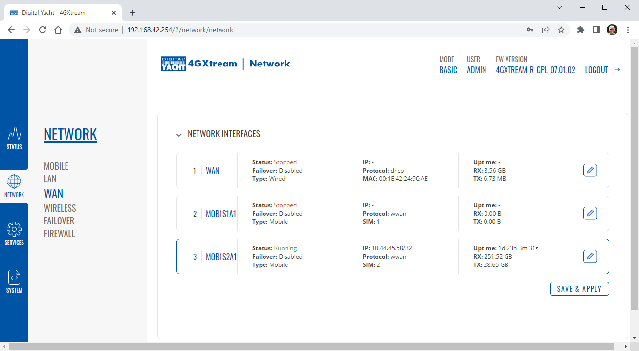
Are you using the right 4G Xtream model in the right region?
We have two models of 4GXtream and with the global world we now live in, we do occasionally get situations where a customer has bought a US unit and tried unsuccessfully to use it in Europe or vice versa. To check what model you have, go to STATUS>SYSTEM and check the device’s Product Code; RUTX11 0***** indicates a European/ROW model and RUTX11 1***** indicates a US model….

Is the 4GXtream reading the SIM card correctly?
Go to STATUS>NETWORK>MOBILE and check that the correct SIM card slot is selected and that the SIM is shown as “Inserted”, the network operator is shown and the Operator State is shown as Registered(Home) or Registered(Roaming) depending upon which country you are in.
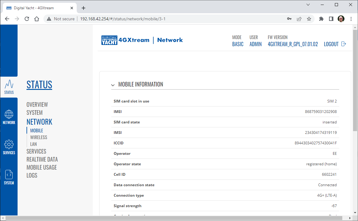
Is 4G Xtream getting a good signal strength?
If you go to the STATUS>OVERVIEW page, in the Modem panel, there is a signal strength indicator in the top right corner and this should be showing a good signal strength of between -40dBm and -90dBm.
Don’t forget that as these are negative numbers, -40dBm is much better than -90dBm. Once you start getting signal strengths in the -97dBm to -110dBm range, your signal strength is not going to be good enough for a reliable internet connection. If you are seeing poor signal strengths but are in a good signal strength area, then we will need to look at antennas and cabling.
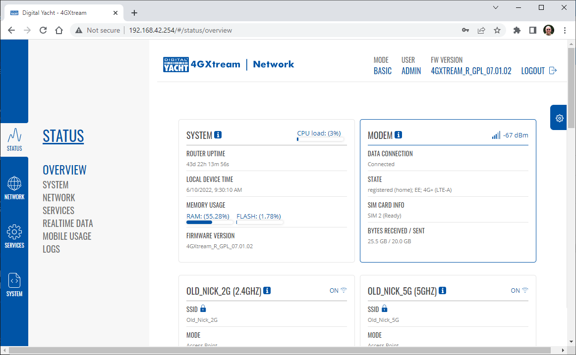
4G Connect
How to configure the LAN port address?
To change the IP address range used on the LAN network, go to NETWORK>LAN and then click the EDIT option. Set as shown below and click SAVE&APPLY. When the unit reboots, reconnect and access the web interface at the address you have set. In the example below, we have set the addres: 172.31.0.1 so when we reboot the unit, to access the web interface in our example, we need to write the address http://172.31.0.1
The DHCP range is set automatically, but if they want to check or change this, go back to NETWORK>LAN and click EDIT and the DHCP settings are in the Firewall Settings tab.
Slow internet speed through WiFi on my 4G Router
If you have a very low internet speed (less than 5m/sec) then several factors can interfere with your internet speed.
When a device is connected to one of our wireless 4G routers, the router has to “route” the data, which takes time. The typical 2.4GHz speed of 50Mbps is shared across all devices on the wireless network: more devices, less speed
It is not uncommon for other 2.4GHz wireless networks to be present on a modern boat; MFD, Charger/Inverter, AIS, etc. Each network, will potentially cause interference and slower speeds
To get a better speed, the best solution is to connect your laptop via Ethernet. With the 4G Connect Pro, you can get internet up to 60m/s via Ethernet but via WiFi, a good connection would be 25-35Mbps.
- The first step is to check all your installation. Make sure there is no interference with your device’s 4G antennae (a nearby radar, for example). Antenna height is not as critical as VHF and better to mount lower and not increase antenna cable length. If installation demands longer cables we can supply 10m or 20m LMR400 cable assemblies. Don’t extend the standard 7m LMR200 cables.
- Then, you should run a speed test on a wired device. Connect a device to the LAN socket of the 4GConnect via a network cable – this gives maximum speed and then do a speed test.
- Another action is is to do a Wi-Fi Survey to see if you are getting interference and congestion. An external Wi-Fi network might interfer with your 4G router network and affect your internet speed. You can do a Wi-Fi survey test with the following article.
Boat remote access thought 4G – Port Forwarding to remote view CCTV system
Although the approach you are taking with DDNS and Port Forwarding would work well on a conventional land based network, that is connected to the internet via a Cable/ADSL router, there are several reasons why they may not work on a mobile network:
- NAT (Network Address Translation): Mobile networks, especially those using IPv4, typically employ NAT to conserve IP addresses. NAT allows multiple devices to share a single public IP address. When you connect a device to a mobile network, it is assigned a private IP address that is not directly accessible from the internet. This makes it challenging for DDNS and port forwarding to function properly, as the mobile network’s NAT may not forward incoming connections to your device.
- Carrier-Level Restrictions: Mobile network providers often impose restrictions on certain network activities for security or network management purposes. These restrictions can include blocking or limiting incoming connections to devices on their network. As a result, even if you set up DDNS and port forwarding correctly on your mobile device, the carrier may still prevent external access to it.
- Firewall and Security Policies: Mobile networks commonly implement firewalls and security policies to protect devices on their networks from potential threats. These security measures may include blocking certain ports or protocols by default, which can interfere with port forwarding. Additionally, some carriers may employ strict security policies that prevent the modification of network settings necessary for DDNS or port forwarding to work properly.
- Dynamic IP Addresses: Mobile networks typically assign dynamic IP addresses to devices. This means that the public IP address assigned to your device can change periodically or when you reconnect to the network. DDNS relies on associating a domain name with your IP address, so if your IP address changes frequently, the DDNS service may not be able to keep up and point to the correct IP address for remote access.
It’s worth noting that some mobile network providers may offer specific plans or services that allow for more open network access or even static IP addresses, which can facilitate DDNS and port forwarding. However, these options may come with additional costs and may not be available on all networks or in all regions.
Overall, the combination of NAT, carrier restrictions, firewall policies, and dynamic IP addresses on mobile networks can make it challenging for DDNS and port forwarding to function reliably. If you require remote access to devices on a mobile network, you may need to explore alternative solutions such as VPN (Virtual Private Network) or cloud-based services that facilitate remote access without relying on DDNS or port forwarding.
Our 4G products (4GConnect and 4GXtream) provide good internet connectivity over 4G mobile networks and we know that they are used by some of our customers to remotely access their marine systems.
To remotely access the systems on a boat, the normal method is for the equipment on the boat to initiate a secure connection to a cloud server and then you use an App on your mobile device to also access the cloud server. The cloud server then routes you through to your boat’s data, which you can view in almost realtime. This method relies on the equipment manufacturer creating the cloud system and app to make this happen. The best example of this type of system is the Victron VRM system.
The second method is to use a VPN service to create a more generic cloud connection, not specific to one manufacturer, which basically connects your mobile device to the boat’s Ethernet network. Once the VPN connection is established, you can remotely do anything that you would normally do when on the boat.
Setting up a VPN on our 4G Products is possible, but requires networking knowledge and is not something that Digital Yacht is able to provide support on. You would need to find a suitably experienced IT networking engineer.
If you want to explore the VPN solution, I would recommend ZeroTier which can be installed on our 4GXtream and is a free and relatively easy to setup VPN service, that I played with a few years back. OpenVPN is also supported on our 4GXtream.
Manual APN Settings for latest EE SIM cards
Since the end of 2022, we have started receiving support requests from new EE customers that cannot get their Digital Yacht 4G Products to work with their EE SIM.
It would appear that recent EE SIMs have a Virgin Mobile profile included, which is seen as the default APN settings when our products are set to Auto APN mode (default). If your SIM is being correctly read, you are getting a good mobile signal strength, the STATE is shown as “Registered (home); EE; 4G (LTE)” but the DATA CONNECTION is shown as Disconnected, then please try the following settings.
Open a browser, go to http://192.168.1.1 and login to the web interface. Now change to ADVANCED mode by clicking on the word BASIC in the top right corner of the web interface. On the menu select NETWORK>INTERFACES and you will see the page below….
Click on the “Pencil” Edit icon for the SIM slot the EE SIM is inserted in – MOB1S2A1 in the example above.
Now you need to set Auto APN to OFF and enter the following details in the boxes that appear. Also make sure that PDP Type is set to IPv4 Only and not IPv4/IPv6 which is the default…
Once all of the settings are correctly entered, scroll to the bottom of the page and click the “SAVE & APPLY” button. Give the unit 20-30 seconds to apply the settings and reboot the modem and then you should see the DATA CONNECTION change to Connected and you will be online.
Connecting other Marine Electronic Equipment to our 4G Products
Many products from leading marine electronics manufacturers now feature a wired and/or wireless network interface. In some larger systems such as those from Navico/Garmin/Raymarine/Furuno, the MFDs, radar scanners, cameras and sonar systems will all be networked together via Ethernet cables. When one of our 4G Products is used as the central wireless router for internet connectivity, some customers have been confused as to whether they can join all of the devices together on one common network.
In general, unless indicated differently by the MFD manufacturer, it is best to leave the manufacturer’s wired Ethernet network, just for connecting the manufacturer’s equipment together and if you want to provide the system with an internet connection, to do this by connecting the master MFD wirelessly to our 4GXtream.
This will result in having two wired Ethernet networks on the boat, one for the navigation equipment and the other for internet access and normal IT type networking, but it will result in the most reliable operation of the two networks.
Most MFD manufacturers do not want customers to open up their Ethernet network to either a conventional LAN or WAN environment that they have no control over. Unknown network devices, levels of network data and protocols, can create interoperability issues that the manufacturer has never tested for, potentially having a serious, negative effect on the operation of their equipment.
The MFD’s wireless interface will be on a separate subnet and “locked down” so that it just does what they need it to do and no more. When you tell the wireless interface to join another wireless network in STATION (STA) mode, rather than its default ACCESS POINT (AP) mode, it will get an IP Address for the wireless interface from the 4GXtream and be able to go online for updates, weather data, etc.
4GConnect Power Consumption
The following power consumption figures are applicable to both our 4GConnect and 4GConnect Pro models. Power consumption does vary significantly, depending upon the amount of mobile data being transferred and how much wired/wireless network activity is taking place.
Below are the average consumption figures for 12v and 24v systems…
Minimum – Powered up but no mobile or network data transfer = 1W
Normal – Powered up with a couple of network devices doing light internet access = 1.5W
Maximum – Powered up with multiple network devices doing heavy internet access = 4.25W
Advanced Diagnostic Tests for our 4G/5G Products
In some situations, our 4G Products can appear to be connected to the internet, but due to other external conditions such as AV Software, ISP issues or local network settings, you cannot access websites from your browser. If this happens, there are some additional tests and checks that can be carried out.
Go to SYSTEM>ADMINITSTRATION>TROUBLESHOOT and do the following tests….
PING TEST
Enter an IP address of 1.1.1.1 and click the PERFORM button. This sends a series of data packets directly to a public website (Cloudflare) which then sends them back to your 4G Product over the Mobile network. The results are shown in the box below and if all of the packets are received, then the connection is good and it might be a DNS issue – continue to the Trace Route Test.
Traceroute Test
Change the method to Traceroute and the address to www.google.com and click the PERFORM button again, you should see the following info in the box that traces, the route through the internet to the Google web server. If the test fails and the Google site is not reached, then you may have a DNS setting issue on your wireless device. Try setting it to use a fixed DNS server address of 8.8.8.8 which is the Google public DNS server.
Check SMS Messages
Sometimes, it can be an issue with your mobile network operator account that is stopping the internet access. Please check if you have received any notification SMS messages from the Mobile Operator that might explain why we are connected but not getting a good internet connection? To do this, go to SERVICES>MOBILE UTILITIES>MESSAGES and you should see any SMS messages that the Mobilke operator have sent you…
Finally, some anti-virus, VPN or network security software has been known to block mobile internet connections, particularly common on business computers. Try temporarily turning off any anti-virus, VPN or network security software and see if that fixes the problem. If it does, make sure that your new 4G Product is in the list of “Safe Networks” in your anti-virus/security software.
Generating Diagnostic Information on our 4G/5G Products
Our 4G Products are used globally on lots of different networks and occasionally, due to incorrect APN settings or SIM card issues, a unit will not correctly register on the mobile network and no internet connections will be available.
In this situation, please start by checking the SIM card, as per this article that we published on our blog…
https://digitalyacht.net/2022/08/12/getting-correct-sim-cards-4g-products/
If that does not resolve the situation, then in order to assist you our support team will need the following screen shots and information…
- A screen shot of the STATUS>OVERVIEW page – first page that you see when you log in to the web interface.
- A screen shot of the STATUS>NETWORK page which lists all of the mobile network info.
- The unit’s troubleshooting file, go to SYSTEM>ADMINISTRATION and then go to the Troubleshoot tab. Scroll down the page and click the Troubleshoot File DOWNLOAD button. Send us the GZIP file that it downloads to your device.
How to tell what firmware your 4GConnect or 4GXtream has?
The firmware version is normally displayed in the top right hand section of any of the web pages….example below of the original 4G Connect “Black & White” web interface and the latest “Blue & White” web interface…
The 4G Xtream only has a “Blue & White” web interface.
VPN on our 4G Products
Setting up remote access to any network that is operating on a mobile LTE (3G/4G) network is never easy, even for experienced IT engineers. Unfortunately, Digital Yacht just do not have the resources or depth of knowledge to support our customers in doing this on an individual basis.
When your remote network is “hidden” inside a mobile network that abstracts all external connections to the internet, the only way to create a VPN is for the 4GConnect/4GXtream to initiate a connection to your VPN server or shared cloud server that does the data routing for you.
Our 4GConnect is based on OpenWRT, which supports two different VPN services; OpenVPN and ZeroTier, plus a couple of tunnelling protocols that could be used as an alternative to VPN. If you do not have the services of an experienced IT engineer to help with setting up a solution, then I would look for examples of connecting to a remote OpenWRT network over LTE using VPN services.
Here is a link to the OpenVPN documentation on the OpenWRT site and it covers using either a Client or Server setup. Hopefully with this information you will be able to find the relevant settings in our 4G products to setup your VPN.
https://openwrt.org/docs/guide-user/services/vpn/openvpn/start
I want to set up my AT&T Sim card
If you have an AT&T Sim Card, then you need to be in “Advanced” Mode, click the word “Basic” in the web page header and then go to Network>Mobile and set the Service Mode to “4G (LTE) Only” and then click the “Save+Apply” button at the bottom of the page….
After the new settings have been applied, go to Network>Interfaces and then click on the “Pencil” Edit button of either MOB1S1A1 (SIM1) or MOB1S2A1 (SIM2) depending upon which SIM slot the AT&T SIM is in….
In the Pop-Up settings window, turn off the Auto APN switch and some new boxes will appear. Select “Custom” from the drop down APN list and then type “Broadband” in the Customer APN box exactly as written with a capital B and then click the “Save+Apply” button at the bottom of the page…
After the settings have been applied, go to Status>Overview and check in the Modem panel that you are connected.
Now try going to another website to check you have internet.
4GConnect Status LEDs Information
Here is some additional information on the modem LEDs inside the 4GConnect box.
Power LED
The power LED is located on the bottom left corner of the front panel, just under the power connector:
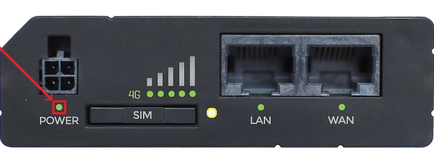
It can perform two different actions:
| ACTION | DESCRIPTION |
| LED turned ON | Router is powered up |
| LED turned OFF | Router is not powered up |
Ethernet port LEDs
The Ethernet port LEDs are located on the router’s front panel, under each respective Ethernet port:
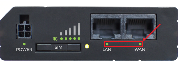
They represent activity happening on the router’s Ethernet ports:
| ACTION | DESCRIPTION |
| LED turned ON | Operating as a 10/100 Mbps connection |
| LED turned OFF | No link established |
| LED blinking | Connection established and there is activity on this port (data being transferred) |
| LEDs light up and turn OFF in sequence from WAN port to LAN1 port | The router is in the bootloader menu state* |
* The bootloader menu is a special router state from which certain upgrades can be performed.
Connection status LEDs
The connection status LEDs are located on the left side of the front panel, between the power connector and the signal strength indication LEDs:
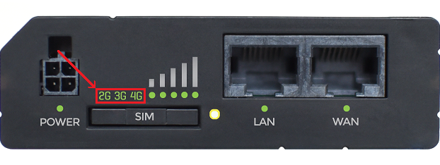
he LED displays the router’s current connection state and network type among a few other things:
| ACTION | DESCRIPTION |
| 2G, 3G and 4G LEDs blinking every 1 second | No SIM or bad PIN |
| Blinking from 2G LED to 4G LED repeatedly | SIM holder is not inserted or access to network is denied |
| 2G/3G/4G LED blinking every 1 sec | Connected to 2G/3G/4G, no data session established |
| 2G/3G/4G LED turned on | Connected to 2G/3G/4G with data session |
| 2G/3G/4G LED blinking rapidly | Connected to 2G/3G/4G with data session and data is being transferred |
Signal strength LEDs
The signal strength LEDs are located in the center of the front panel, to the right of the connection status LEDs:
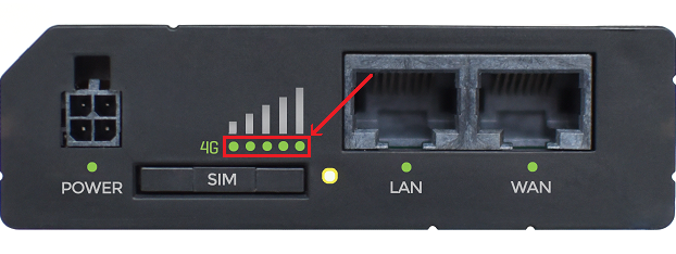
Each lit up LED represents a different value of the router’s current signal strength in RSSI:
| NO. OF LIT UP LEDs | SIGNAL STRENGTH VALUE |
| 0 | ≤ -111 dBm |
| 1 | -110 dBm to -97 dBm |
| 2 | -96 dBm to -82 dBm |
| 3 | -81 dBm to -67 dBm |
| 4 | -66 dBm to -52 dBm |
| 5 | ≥ -51 dBm |
The signal strength LEDs can also be used as a time indicator for holding the reset button. When you press and hold the reset button, you have to hold it pressed for 5 seconds (by default) to initiate a factory reset. Each second, a new signal strength LED lights up. When all 5 LEDs are lit up, it represents that 5 seconds have passed since you pressed down on the reset button and that you can release it.
After releasing the button, all 5 LEDs will start blinking every 1 second. This signifies that the router has begun the factory reset.
After the router gets powered up, all signal strength LEDs will turn ON and stay ON for about 40 seconds or until the router’s modem registers on a network – after this, the LEDs will start displaying the router’s current signal strength.
4GConnect Mobile Network Disconnection
If you have a good internet on your 4GConnect, but then the internet connection drops out after a period of time, then this section is for you. Also this is useful for fishermen or blue water sailors who regularly go a long way off shore and then when they return within reception range the 4GConnect does not automatically reconnect.
The part below is for the 4G Connect with the black and white interface.
First, make sure that “Force LTE Network” and also “Reregister” are both ticked and a time period of 300 secs – as per image below….
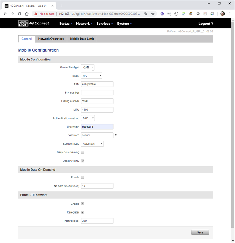
If that does not fix things, then please proceed to the Ping Reboot configuration procedure below.
Ping Reboot Configuration
To enable the “Ping Reboot” feature, go to SERVICES>AUTO REBOOT and you will see a similar page to the one below…
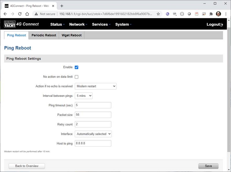
I suggest you use the same settings as shown above, which are the ones I have used in all of our testing. Every 5 minutes, it pings 8.8.8.8 which is the Google public DNS server and is always online.
If it does not receive a reply within 5 seconds, it retries two more times and if there is still no reply it restarts the 4G Modem.
General Information on 4G/5G Products (Configuration, updates, SIM cards)
If you have any issue with your 4G product then It is always worth updating your 4G Product to the latest version. This article, although written about the AT&T update, is still applicable for any unit.
Updating 4G Firmware
Please note that older 4GConnect units must do a two stage update to go from the first “Black and White” web interface version, to the latest “Blue and White” web interface version. The V01.14.05 is a special intermediate version (last of the “Black and White” generation) that must be loaded first, in order to make the jump to the new V07.02.08 firmware.
https://digitalyacht.net/2022/03/04/important-update-4g-products/
Configuring 4G Product
Here is the link to the very useful video on configuring our 4G Products – shows the latest “Blue and White” web interface…
https://digitalyacht.net/2022/03/04/important-update-4g-products/
Getting the correct SIM card
Here is the most recent article on SIM cards. If the customer is getting a good mobile phone signal on the 4G Product and the SIM card is being read, the network operator is recognised, etc. then it could be a SIM issue and this article explains what needs to be checked…
https://digitalyacht.net/2022/08/12/getting-correct-sim-cards-4g-products/
How to manually reset the 4GConnect?
Manual Reset for 4G Connect
To reset one of our 4GConnects, you need to locate the 4GConnect main unit (silver aluminium box with black end caps) and then on the Antenna end cap, there is a small hole to access the reset switch inside – see red square in image below….
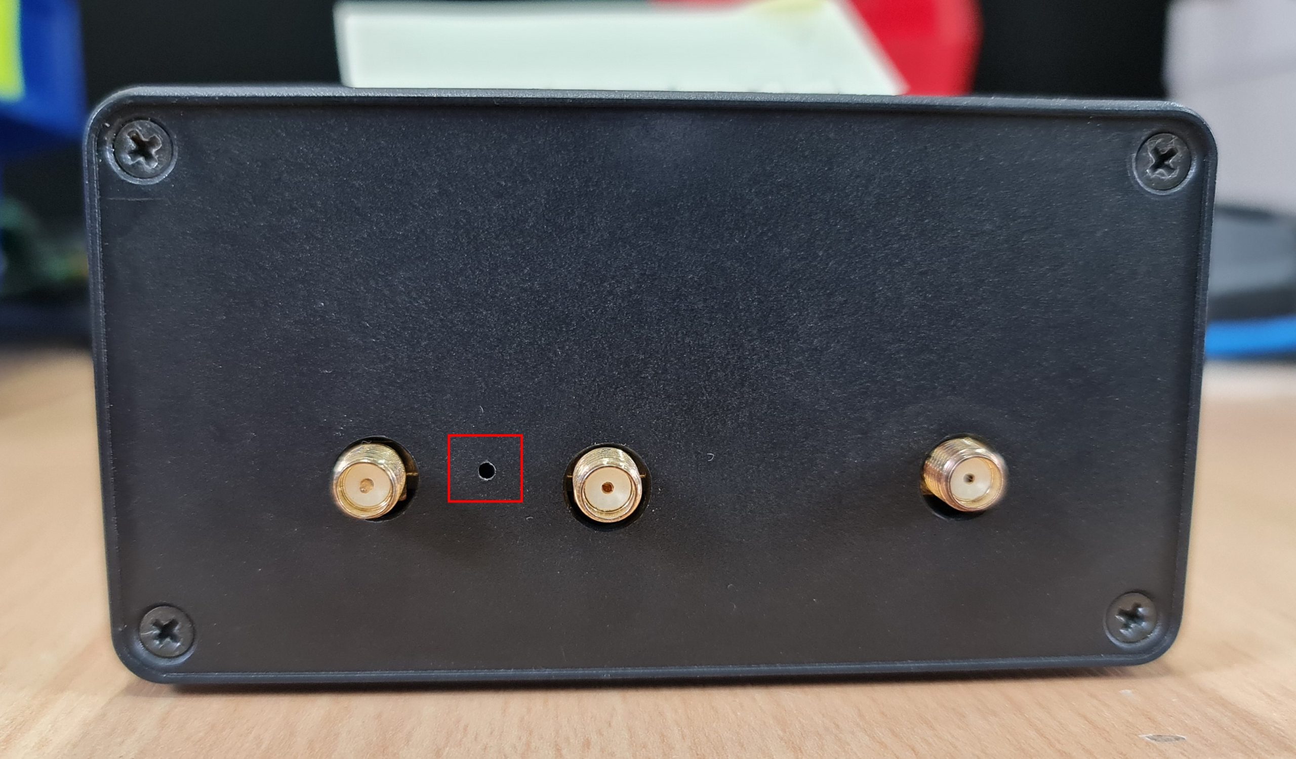
NOTE – If you have an older 4GConnect, which did not have the reset hole in the antenna end panel, then go to the next section.
With the unit fully powered up (allow 45-60 seconds from turning on the power), use one of those iPhone reset tools or failing that an opened up paper clip, to gently push inside the hole. You will feel a slight resistance and if you continue to gently apply pressure, you should feel the push switch depress (only about 1/32”) and when you do, keep the reset switch depressed for 10-20 secs.
When you release it, the 4GConnect should reboot and when it powers back up, all of the settings will be reset to the original ones when it left our factory.
The SSID and wireless password will be back to 4GConnect and you should be able to connect wirelessly to it and access the web interface at http://192.168.1.1 where you can sign in with password is 4GConnect again.
The only settings I would recommend changing are the APN settings for whatever mobile network SIM you are going to use and then the wireless network name (SSID) and wireless password so that the system is secured so only the owner and friends can connect to it and not anyone who has read the 4GConnect manual and found the default settings.
Manual Reset for older 4G Connect
To manually reset an older 4GConnect that does not have the reset hole in the antenna end cap, you will need a cross head screwdriver to remove the enclosure end cap that has the three antennas on it.
The procedure should be carried out with the 4GConnect powered up, so if you are not doing this on the boat, you will need a 12v 1A DC Power Supply.
First unscrew the three antennas (or antenna cables if you have a 4GConnect Pro), by using your fingers on the knurled ring at the base of the antenna…
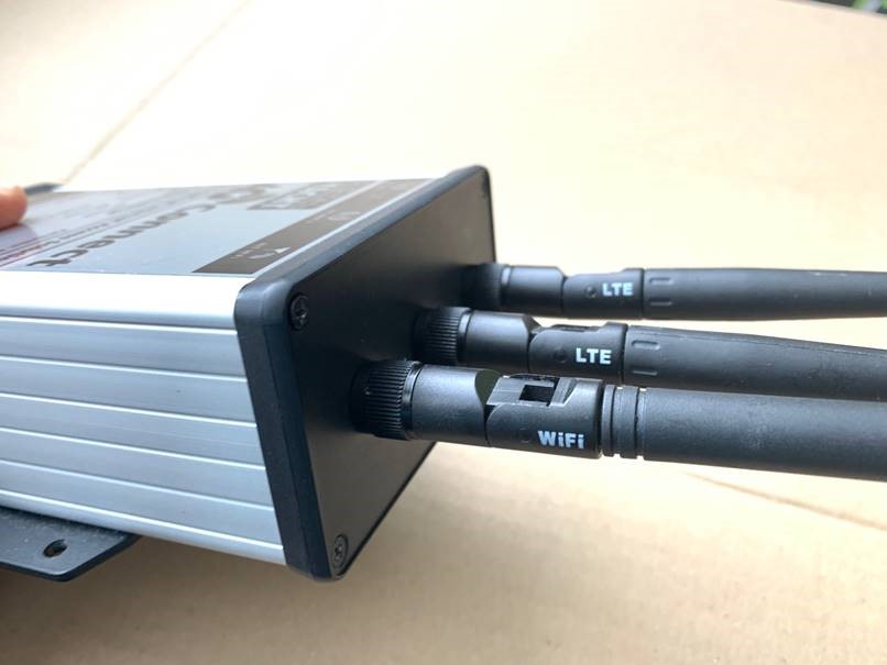
Once the antennas are removed, unscrew the 4x cross head machine screws that hold the end cap on…
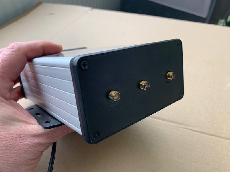
Gently pull the end cap away from the aluminium enclosure, being careful not to put unnecessary pressure on the three connectors…
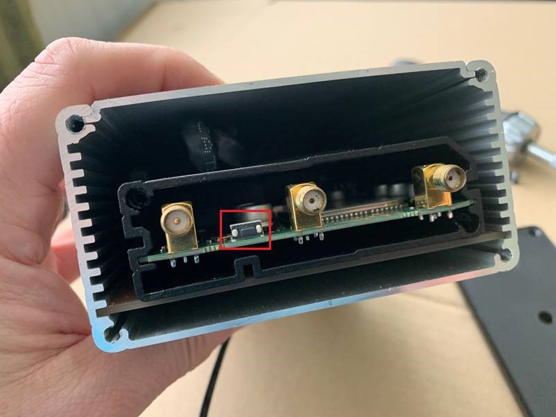
The reset switch is highlighted in the image above within the red rectangle. Press and hold this switch in for 10-20 secs and when you release it, the 4GConnect should reboot and when it powers back up, all of the settings will be reset to the original ones when it left our factory.
The SSID and wireless password will be back to 4GConnect and you should be able to connect wirelessly to it and access the web interface at http://192.168.1.1 where you can sign in with password is 4GConnect again.
How to configure our 4G products?
Since COVID forced many of us to start working remotely, we are seeing an ever increasing demand for our 4G Products. Once installed and working, these products are extremely reliable, but with so many mobile network operators around the world, initial setup can be confusing. To help our customers get up and running as quickly as possible, we have created a new video on configuring our 4G Products.
This video is filmed using one of our 4GXtream products, but is equally applicable for our 4GConnect and 4GConnect Pro products, particularly if you have updated to the latest V07.01.02 firmware as detailed in a previous post “Important Update for our 4G Products”. This update adds the same, new “Blue and White” web interface to our 4GConnect, as our 4GXtream has and will be the interface that all future videos and technical documents will be based on.
How to insert a SIM card into 4G Connect?
Here’s a quick video showing how to insert a SIM card into the 4G Connect. It also shows how to view the software to check the SIM is registered with the network
How to override the Auto-APN Settings?
Our 4GXtream router but also the latest 4G Connect version have a new “Auto-APN” feature that reads the SIM details and selects the correct APN settings for the SIM’s mobile network. APN stands for Access Point Name and are the settings your 4G product needs to pass to the network carrier; AT&T, Vodafone, T-Mobile, etc. in order for the carrier to allocate your 4G product an IP address and connect you to the right secure network.
On many networks the new “Auto-APN” feature works very well, but today we had a Vodafone customer contact us who could not get their 4GXtream to connect correctly. The solution was to manually override the APN settings, by following the procedure below.
- Go to the 4GXtream/4GConnect’s web interface at http://192.168.1.1 and login
- By default the 4GXtream or 4G Connect is in “Basic” mode and you need to click on the word Basic in the top right hand section of the web page, to enable “Advanced” mode.
Now go to NETWORK>INTERFACES and click on the Edit button (pencil icon) of the SIM card interface you are using, SIM 1 in the example below.
You can now edit the SIM settings to disable Auto-APN mode and add manual “Custom” APN settings, as shown below which are the correct settings for a Vodafone UK (contract) SIM. Once you have set the manual APN settings click the “Save & Apply” button and once the settings have been changed, go to the STATUS>OVERVIEW page to see if you now have a connection to the internet.
If your network carrier has not given you your APN settings, then this is a pretty good site to try and we would be really grateful if you could let us know if the Auto-APN settings work for you or what manual settings you had to use.
Getting the Correct SIM cards for our 4G Products
One of the most common problems, that the Digital Yacht support team help our 4G Product customers with, is SIM card issues. This little piece of plastic, with its integrated memory chip, containing a unique identifier, that allows your data usage to be tracked, causes a disproportionate amount of wasted time and effort, so we decided to publish a guide to avoid the pitfalls that we regular see.
Not all SIMs are created equal and with the majority aimed at mobile phone users, it is important that the SIM you use in our 4G Products meet the following criteria….
- It is a 4G SIM (not 5G)
- It is a Data Only SIM – designed for wireless routers and not mobile phones
- The SIM should not have a PIN number enabled or if it does, that you know what it is
- The SIM has not reached its Data Limit
- That the SIM is properly registered and enabled by the network operator
- If being used Internationally that the SIM has roaming enabled
Once you are confident that your SIM meets all of the above criteria, please insert it in to our 4G Product and using the web interface, go to STATUS>NETWORK where you should see a screen similar to the one below, minus the red annotations….
The key pieces of information to look for on this page are that the SIM Card State shows “Inserted”, which means that it has been read by our 4G Product. Then you should see the IMSI and ICCID numbers, which are stored on the SIM and used by the 4G Product to identify itself to the network operator.
- IMSI = International Mobile Subscriber Identity. This is a unique identifier that defines a subscriber in the wireless world, including the country and mobile network to which the subscriber belongs. It has the format MCC-MNC-MSIN. MCC = Mobile Country Code (e.g. 310 for USA); MNC = Mobile Network Code (e.g. 410 for AT&T), MSIN = sequential serial number. All signaling and messaging in GSM and UMTS networks uses the IMSI as the primary identifier of a subscriber.
- ICCID = Integrated Circuit Card ID. This is the identifier of the actual SIM card itself – i.e. an identifier for the SIM chip. It is possible to change the information contained on a SIM (including the IMSI), but the identify of the SIM itself remains the same.
The IMEI number is unique to the 4G Product’s modem and will always be displayed, even if the SIM is not inserted…
- IMEI is short for International Mobile Equipment Identity and is a unique number given to every single mobile phone, typically found behind the battery. IMEI numbers of cellular phones connected to a GSM network are stored in a database (EIR – Equipment Identity Register) containing all valid mobile phone equipment. When a phone is reported stolen or is not type approved, the number is marked invalid.
Other key information on this page are the Operator and Operator State. The image above was using a SIM from UK operator 3 which was a fully registered, had plenty of Data and had established a data connection.
Assuming that you have followed this guide and selected the right SIM card, then there is one last hurdle to overcome, making sure that our 4G Product is using the right APN settings for the SIM’s network operator. The Access Point Name (APN) settings, vary from network operator to network operator, and with the latest firmware updates, our 4G Products will automatically try and set these from a database of popular APN settings. However, for some networks, it is still necessary to manually enter the APN settings, please see our configuration video for more details.
Once you have everything working, there should be no need to make any further changes to the settings, but occasionally the connection will fail. This can be for a number of reasons, but more often than not, particularly if you are using a Pay As You Go type SIM or you are using International Roaming, it will be a network operator issue and you should check that you have not received an SMS notification from the operator.
To do this, go to the SERVICES>MOBILE UTILITIES>MESSAGES screen where all of the received SMS messages are displayed…
Make sure there are no “Data Limit” or “Roaming” related messages that might account for your loss of connectivity and if you are still having problems after rebooting the modem, which you can do at the bottom of the STATUS>NETWORK page, please contact your network operator to check the status of your SIM account.
Using WL510 with 4GXtream
To decide whether to use the Mobile 4G connection or the WL510 long range wireless connection, you will need to go in to the 4GXtream web interface and click on the Network>WAN menu option….which will display the page below.
You can use the switches at the end of each line to select whether you want to connect to the internet via Mobile 4G or via the WL510 Wi-Fi on the wired WAN interface. In the screen shot above, taken from my boat’s 4GXtream, I do not have an WL510 wireless booster connected to the Wired WAN interface, so it does not show any information about it but on your unit, with the WL510 connected, there should always be an 192.168.10.xxx IP address and uptime values.
Just click Save and Apply after making your selection.
Is the SIM or Network Operator causing the problem?
If the unit has been working and suddenly stops or you have followed the steps above and everything appears to be OK but you still do not have a connection to the internet, then the fault is likely to be with the SIM or network operator. Could any of the following factors be applicable?
- The SIM is a Pay as You Go type and the credit has expired?
- The SIM is a normal mobile phone SIM and not a Data Only SIM which some network operators insist must be used in wireless router type systems?
- The SIM is a monthly contract SIM but has a data limit that you have exceeded?
- You are using the SIM in another country but the network operator has not enabled roaming?
- The SIM is not properly registered?
The only option in this situation is to contact the network operator, which can be a convoluted exercise, but we have seen this situation many times and if you can get through to the right person and tell them the exact nature of the problem, then it can be resolved.
Are the APN Settings Correct?
The best source of APN settings is online at https://apnsettings.org and the best way to search for them is to do a Google search like apnsettings.org UK Vodafone 2022 as the search facility on the website is not great. If the default Auto APN setting on the 4GXtream does not work, manually set the APN settings for your SIM card and save them.
If they are correct, you should see the Data Connection in the STATUS>OVERVIEW page (see above) shown as Connected and in the NETWORK>WAN page, whichever MOB SIM Slot you are using should have an IP address – in the example below MOB1S2A1 has IP address 10.44.45.58/24
WL510
WL510 Configuration File Update
In the fast moving world of wireless technology, our WL510 is quite old now and you might get the message: “err_ssl_version_or_cipher_mismatch” when trying to upload the configuration file. This is due to the age of the firmware as V5.5.8 used TLS V1.0 which is no longer supported in most modern browsers.
The way to get round this, is to use an older computer with an older browser on it.
Once you have an older computer connected and can bring up the WL510 web interface, update the firmware to the latest version and the “err_ssl_version_or_cipher_mismatch” issue will be gone. The latest version of the WL510 firmware can be found here: https://digitalyacht.net/wp-content/uploads/2023/08/XM_v6_3_6.zip
The attached file is a compressed ZIP file containing the latest firmware. Please unzip the single BIN file that is inside as this is the file that you need to upload to the WL510 not the ZIP file.
Login to the WL510 web interface and go to the SYSTEM page. Then browse for the extracted BIN file, select it and then upload it. After the update, you will need to apply the configuration file.
Changing the default SSID and Password on our iNavConnect/iNavHub/iKConnect routers
Connecting our WL510 to a Password Protected type Restaurant/Bar hotspot
Connecting our WL510 to a Captive Portal type Marina hotspot
Configuring a WL510 after a reset (WiFi Procedure)
If you have followed the procedure to reset the WL510 then you must follow the procedure below to reconfigure the WL510.
You must download the product firmware by clicking here.
Configuration Procedure – Wireless Method
After a reset, the WL510 reverts to a factory defaults state and needs to have a WL510 Configuration file uploaded to it (link above).
Your WL510 currently has a fixed IP address of 192.168.1.20 and is not providing Automatic DHCP IP address allocation to any devices that are connected to it. Your iNavConnect/iNavHub/iKConnect is trying to get an IP address for its WAN socket from the WL510 but is failing to do so.
All of our wireless routers use the 192.168.1.xxx range of IP addresses on their LAN network, so the easiest way to talk to the WL510 in this state, is to temporarily unplug it from the WAN socket on the router and plug it in to the LAN socket. Now the WL510, the router and any devices connected to it are all on the same network IP address range (192.168.1.xxx).
Make sure your computer is wirelessly connected to the iNavConnect/iNavHub/iKConnect and then type http://192.168.1.20 in to the address bar of your browser. You should bring up the WL510 login page (see below), but you may get a security warning saying that the security certificate is not valid, but this is because your browser cannot get online to check the WL510’s security certificate, so just proceed…
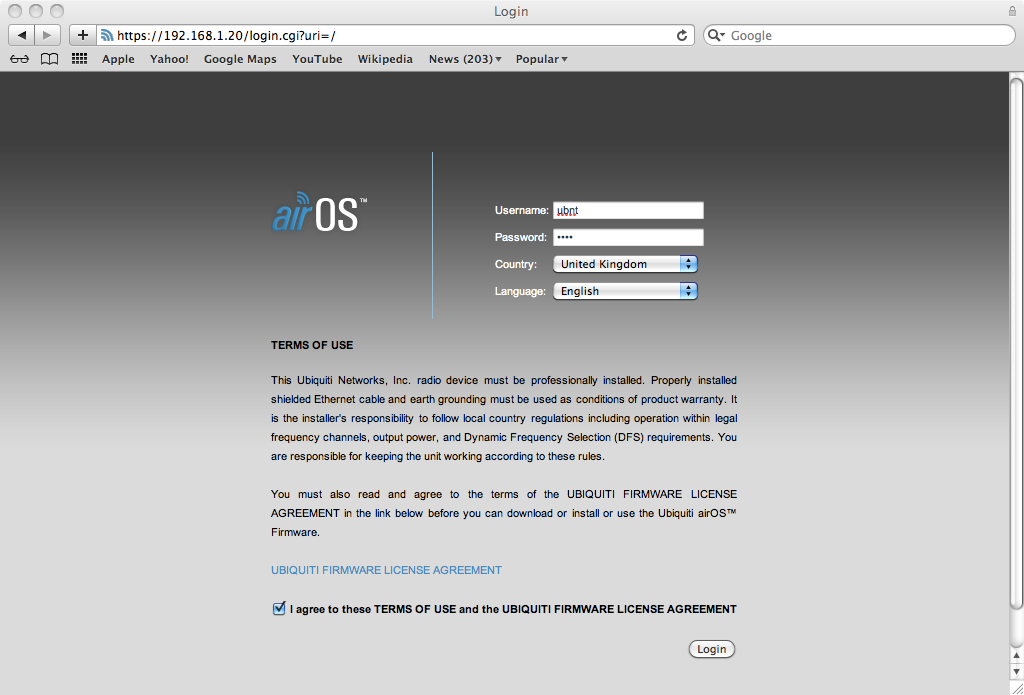
The default Username and Password after a Reset are “ubnt” (without the quotes) and you will need to select your country and also tick the accept conditions box.
Once logged in, dismiss any warning about default administrator password that might appear and go to the “SYSTEM” tab. In the bottom right corner is the Manage Configuration section and you need to click on the “Choose File” button and then select the attached config file, from where ever you saved it to.
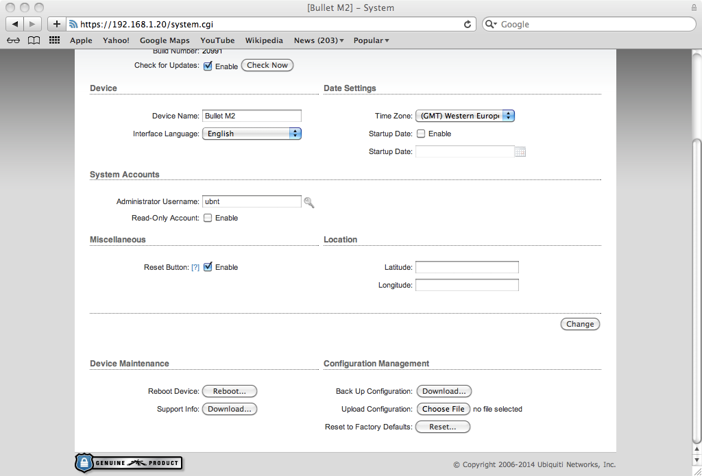
Once selected, click the “Upload” button, followed by the “Apply” button that will appear and the WL510 default configuration will be loaded. It takes about 30 seconds for the WL510 to apply the new configuration and reboot itself with the new settings.
While this is happening, unplug the WL510 from the LAN socket of the router and plug it back in to the WAN socket. When the WL510 has finished rebooting, you should be able to type 192.168.10.20 in to your browser and see the WL510 login page as normal and login using “wl510” as the username and password as usual.
Configuring a WL510 after a reset (Wired Procedure)
If you have followed the procedure to reset the WL510 then you must follow the procedure below to reconfigure the WL510.
You must download the product firmware by clicking here.
Configuration Procedure – Direct Cable Method
After a reset the WL510 has a fixed IP address of 192.168.1.20 and does not provide IP addresses to devices that connect to it automatically. Therefore you will need to connect a PC or Mac to the WL510 using a normal network Ethernet cable and set the computer you are using to temporarily use a fixed IP address of…
Fixed IP address = 192.168.1.2
Subnet Mask = 255.255.255.0
Once you have your computer set to this fixed IP address, it should be on the same network as the WL510 and if you open a browser you should be able to bring up the WL510 login page at http://192.168.1.20
This should take you to the normal Log In screen of the WL510 (see below). The default Username and Password after a Reset are “ubnt” (without the quotes) and you will need to select your country and also tick the accept conditions box.
Once logged in, go to the “SYSTEM” tab and in the bottom right corner is the Manage Configuration section and you need to click on the “Choose File” button and then select the firmware file above which needs to be downloaded, from where ever you save it to.
Once selected, click the “Upload” button and the WL510 production default configuration will be loaded. It takes about 30 seconds for this to happen and for the WL510 to reboot itself with the new settings.
Whilst you are waiting for the WL510 to reboot, put the PC or Mac back to getting the IP address automatically.
Once the WL510 has finished rebooting, your PC/Mac should get an IP address automatically in the 192.168.10.xxx range and you should be able to type http://192.168.10.20 in to your browser and see the login page as normal. At this point the Username and Password will be back to “wl510” as normal.
The above screen shots are from a Mac but a PC should be identical.
WL510 Hardware Reset
First you need to unscrew the four black screws that hold the end cap of the WL510 in – the end cap with no connectors…
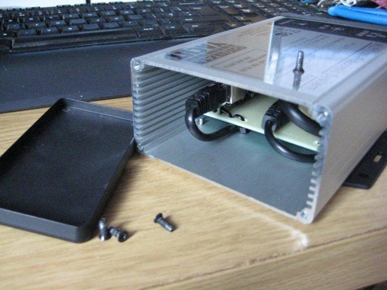
Once the end cap is removed look down in to the unit and you will see the Reset switch which I have highlighted in the red box….
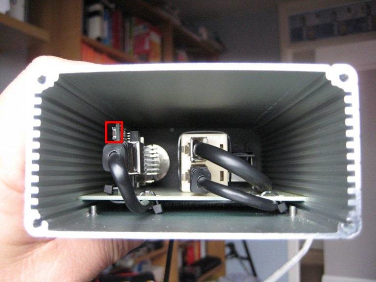
Here is another picture showing the PCB with the six LEDs in the red box and my finger pressing the reset switch….
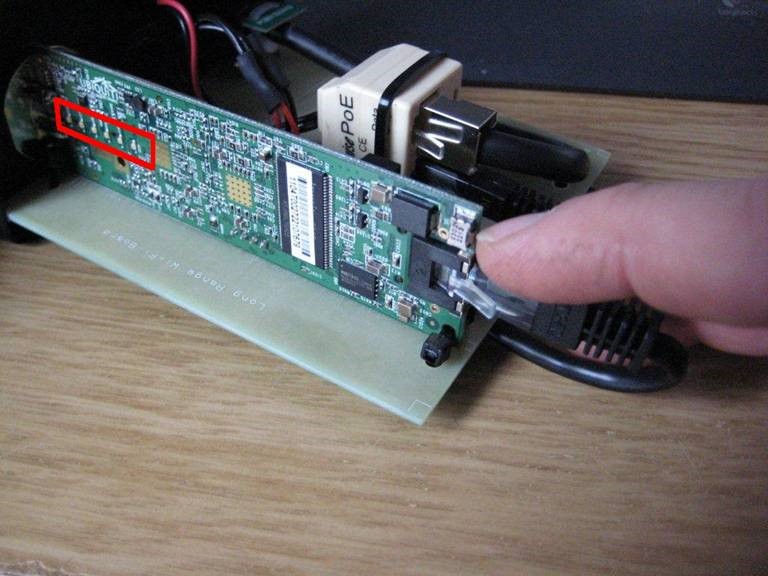
With the WL510 powered up and the end cap removed, press and hold the reset switch for at least 15 seconds.
You should see the reflection of the LEDs on the left hand wall of the aluminium enclosure and normally there are a couple of green LEDs lit and during the 15 seconds you should see all six LEDs flash on, keep holding the reset button in for another few seconds and then release.
You should now wait for about 20-30 seconds for the WL510 to reboot and proceed to the Configuration Procedure below.
After you have reset the WL510, then we need to re-configure it before it will work properly.
Using WL510 with 4GXtream
To decide whether to use the Mobile 4G connection or the WL510 long range wireless connection, you will need to go in to the 4GXtream web interface and click on the Network>WAN menu option….which will display the page below.
You can use the switches at the end of each line to select whether you want to connect to the internet via Mobile 4G or via the WL510 Wi-Fi on the wired WAN interface. In the screen shot above, taken from my boat’s 4GXtream, I do not have an WL510 wireless booster connected to the Wired WAN interface, so it does not show any information about it but on your unit, with the WL510 connected, there should always be an 192.168.10.xxx IP address and uptime values.
Just click Save and Apply after making your selection.
Sensors & Instruments
GPS160
Configuring a GPS160 for 1PPS Output
To do this configuration, it is necessary to open the GPS160. It is recommended that this operation is only carried out by an approved Digital Yacht Dealer/Distributor, any physical damage to the PCB will not be covered by warranty.
Before opening the GPS160, turn off all DC power to the unit and then remove the threaded mount by unscrewing the 3xM3 hex bolts using a suitable Allen Key. Then using a Torx T6 screwdriver, remove the three screws that hold the GPS enclosure together. Gently pull the enclosure apart being careful not to lose the O-Ring seals (1 large outer and 3 small screw pillar O-Rings).
Once the GPS160 PCB is exposed, locate PL3 which is on the underside of the PCB (see below). It is possible using a pair of tweezers to carefully move the “Jumper” from the default NMEA position to the 1PPS position. The second image below shows what a “Jumper” looks like and how it hangs down on the connector.
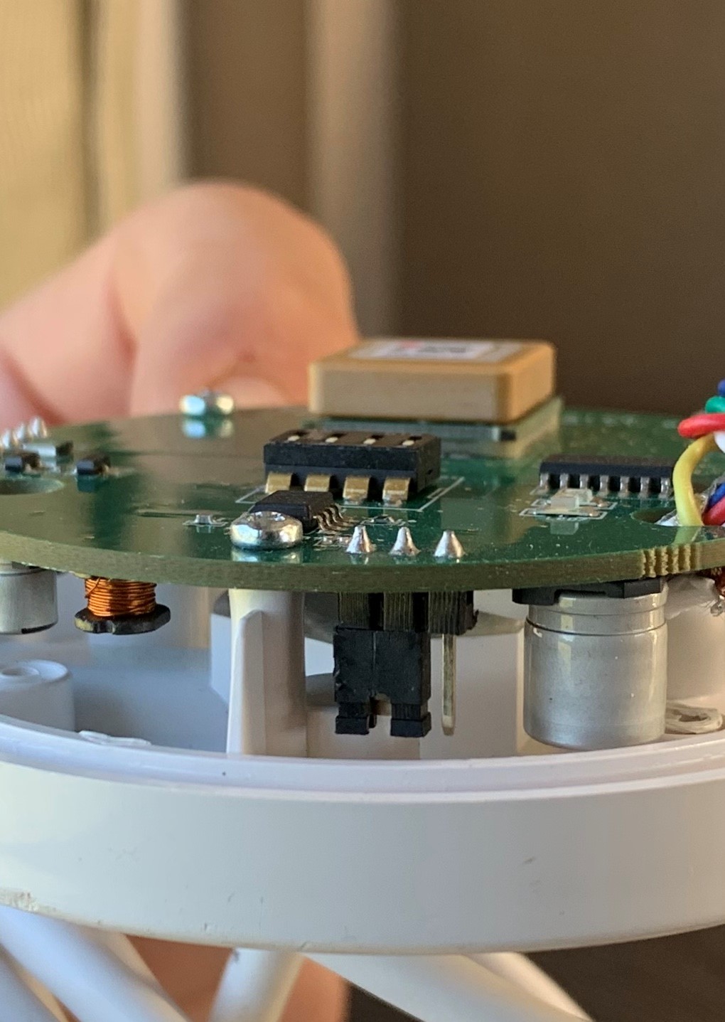
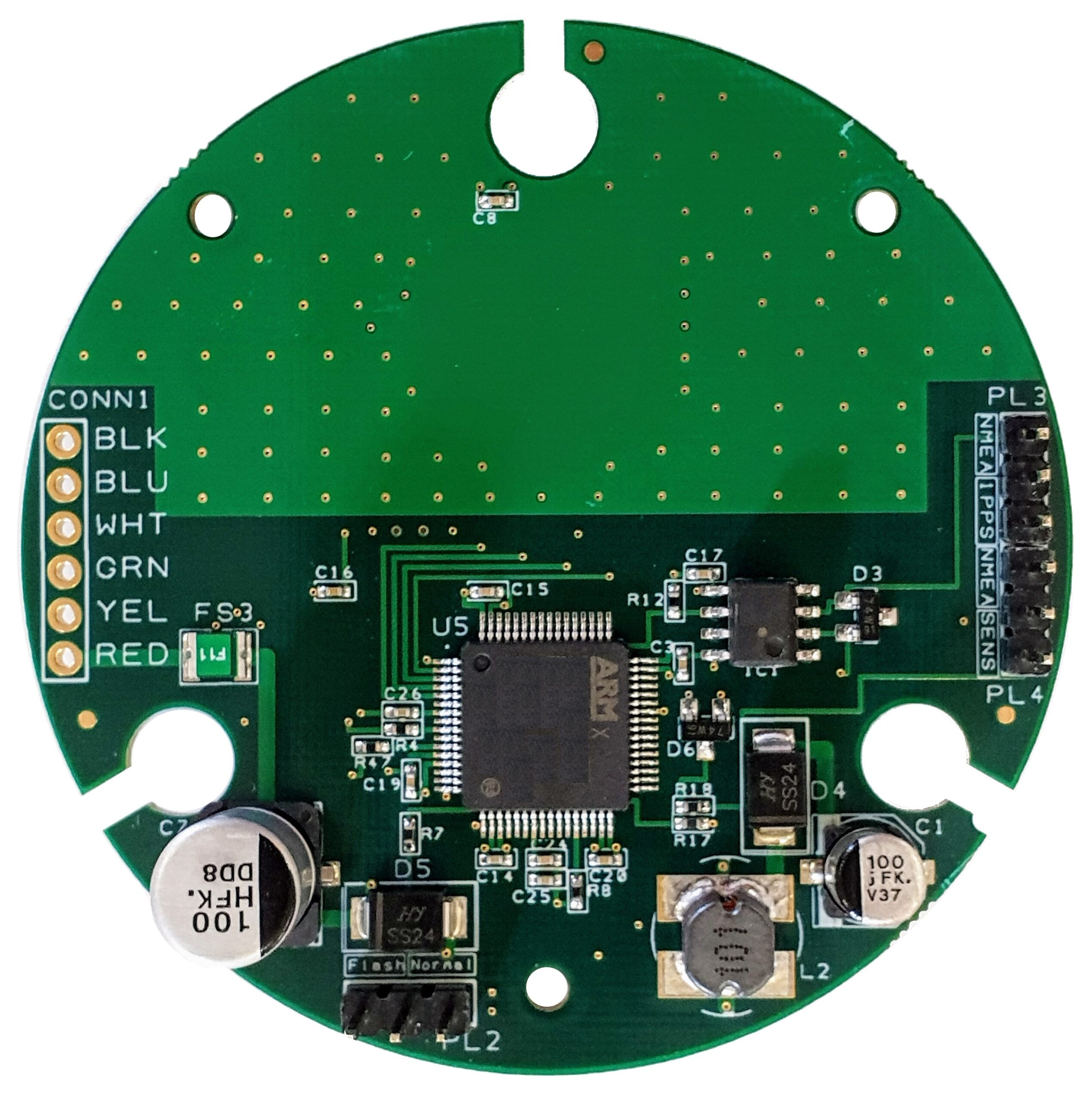
Once the “jumper” has been moved to the 1PPS position, re-assemble the unit, wire the Blue wire to whatever device needs the 1PPS signal and power up the GPS160. As soon as the GPS160 gets a valid position fix, the 1PPS signal will start to be transmitted.
This is the output stage of the 1PPS circuit, note it has a 50mA PTC Fuse that offers some protection, but care should be taken connecting it to other devices.
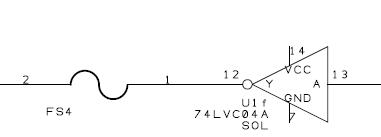
GPS Jamming in Baltic Countries
Some customers have been experiencing Russian GPS Jamming in Baltic countries, where the GPS doesn’t return to the correct location and it has to be fully rebooted.
A way around this is would be to operate the units in GLONASS only mode and this is probably the easiest way to safeguard against GPS Jamming. The signals of the two types of satellites are very close together and it is extremely difficult to jam one frequency and keep the other frequency unaffected.
GPS, the centre frequencies are 1575.42 MHz (L1), 1227.6 MHz (L2) and 1176.45 MHz (L5).
GLONASS operates as frequency divisional multiple access (FDMA) and there are two operational centre frequencies 1602 MHz (L1) and 1246 MHz (L2) and at 1207.14 MHz (L3). GLONASS over this decade will also introduce Code Divisional Multiple Access (CDMA) similar to GPS.
GALILEO has a range of frequencies assigned in the L-band as follows:
E2 – L1 – E1 – Centre frequency 1575.42 MHz (band from 1559MHz – 1591MHz).
E5A – Centre frequency 1176.45 MHz (band from 1164 MHz – 1188 MHz).
E5B – Centre frequency 1207.14 MHz (band from 1188 MHz – 1215 MHz).
E6 – Centre frequency 1278,75 MHz (band from 1260 MHz – 1300 MHz).
Please take a look at the current GPS160 manual, which shows how to change the DIP switches inside the units to make them operate in GLONASS only modes.
GPS160 IP Rating
The GPS160 models (GPS160, GPS160USB, GPS160F etc.) are all IP67 Rated. Units are fully waterproof and designed for permanent mounting outside.
GPS160 SOG reading standing still
This is pretty normal behaviour for a modern GNSS receiver and is a result of position “jitter” caused by multi-path signals and scintillation. Traditionally, older GPS systems used to apply a low pass filter (damping) to the calculated positions and this reduced the SOG and COG fluctuations when stationary.
With the GPS160 and its highly accurate Tri-Data technology, we decided to not apply any damping so that the readings were as accurate and with as little lag as possible. The only down side of this approach is this 0.1 Knot indication when stationary, but as soon as you start moving you get the most accurate and lowest latency output.
Do I need to change the GPS160 Operating Mode?
The default GPS160 operating mode has been optimized to work well with the maximum number of installations. It is operating in “Tri-Nav” mode and will give the same level of accuracy as any of the other “Tri-Nav” modes. In “Tri-Nav” mode, satellites from all three constellations; GPS/GLONASS/GALILEO are used to work out the most accurate possible position.
In over 90% of pleasure boat installations, the default mode is the best one to use and unless you know that your system can accept a faster update rate or can make use of the additional sentences, then we would not recommend that you change mode.
Typical applications where you might wish to change the Operating Mode, are when you are using Yacht Racing Software on a PC, where the higher 10Hz or even 18Hz “Turbo” mode might make the difference between 1st and 2nd place or if you want the system to display the satellite signal strength information.
If the GPS160 is being installed on a commercial vessel, then the “Professional” mode outputs a lot of additional information about the quality of signals, validity of the position, datum, etc. that larger commercial ship systems must have to be sure they are navigating safely. Most pleasure boat systems would not even recognize or know what to do with these extra sentences.
Finally, for specialist applications, where a customer only wishes to receive data from one satellite system, then the GPS160 can be configured to just use GPS, GLONASS or Galileo satellites.
Connecting iKonvert to the GPS160
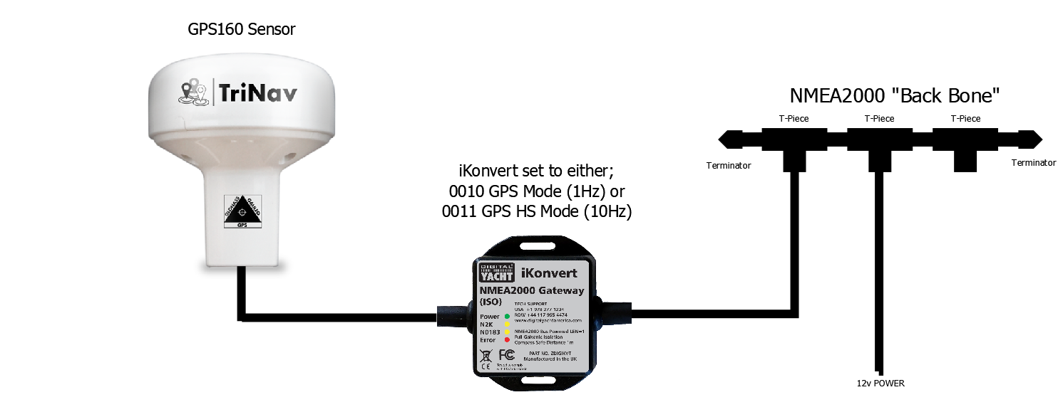
Connecting GPS160 to an NMEA 0183 equipment
Find out how to wire our GPS160 to an NMEA 0183 equipment (GPS, Chart plotter, Fish Finder, AIS, etc.) with this page.
WindSense
Connecting WindSense to an iKonvert
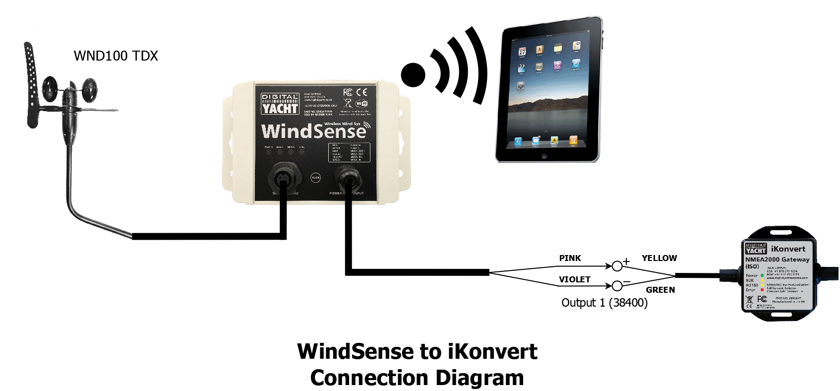
Connecting WindSense to an AIS
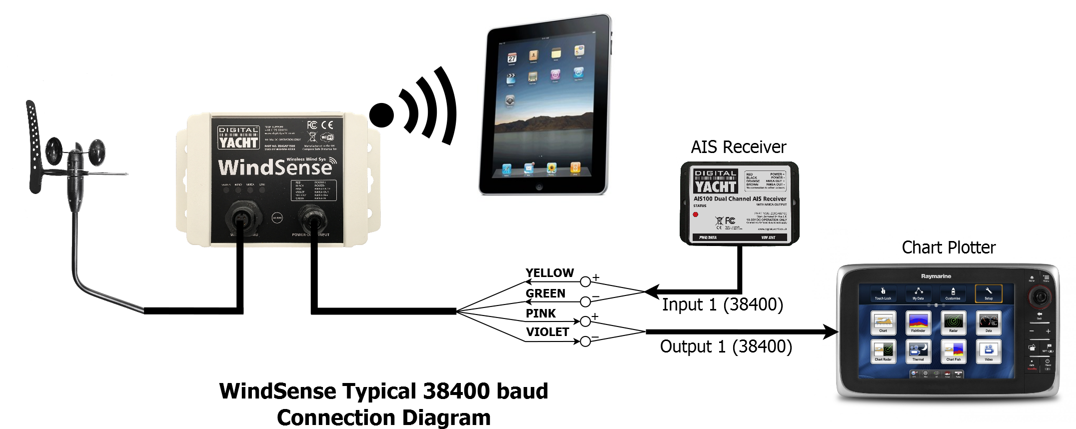
Connecting WindSense to the DST800 & AIT2000
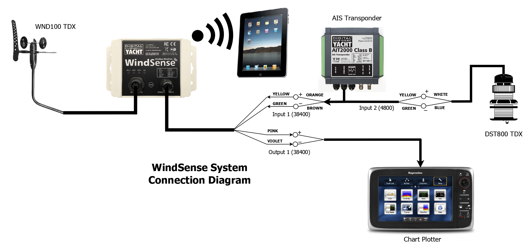
Connecting WindSense to an Instrument
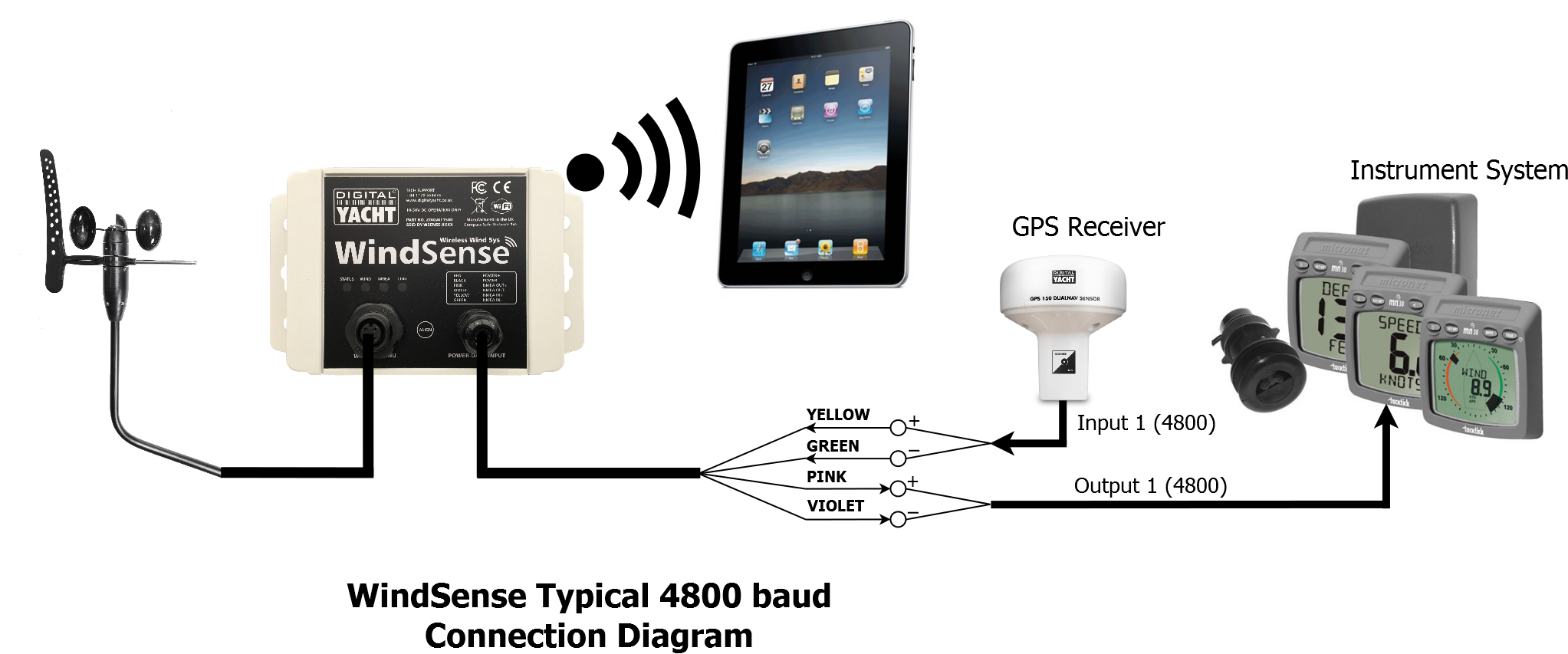
iSeaSense
What’s the WiFi network password?
By default, NMEA to WiFi server’ creates a wireless Access Point (hotspot) on-board your boat. The Name (SSID) of the Access Point will be “NavLink2-xxxx” or “DY-WiFi-xxxx‘, etc, depending on the product you’ve purchased, where xxxx is the unique four digit code of your device.
To connect to the NMEA to WiFi server, you will need to scan for wireless networks, find and select it in the network list and then when prompted, enter the default WPA2 password, which is “PASS-xxxx”, where xxxx is the same, unique four digit code that is in the hotspot name.
For instance, if you have a WLN30 and the WiFi network name created is DY-WiFI-D4B7 then the WiFi network password is: PASS-D4B7
Connecting WND100 to iKonvert
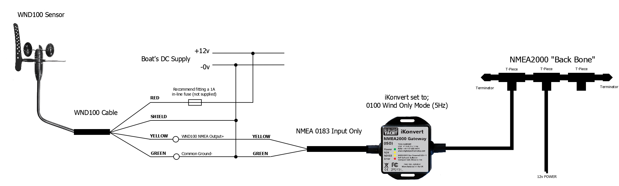
WND100
How to connect the WND100 to an AIS transponder?
![]()
How to connect WND100 to a Port Com?
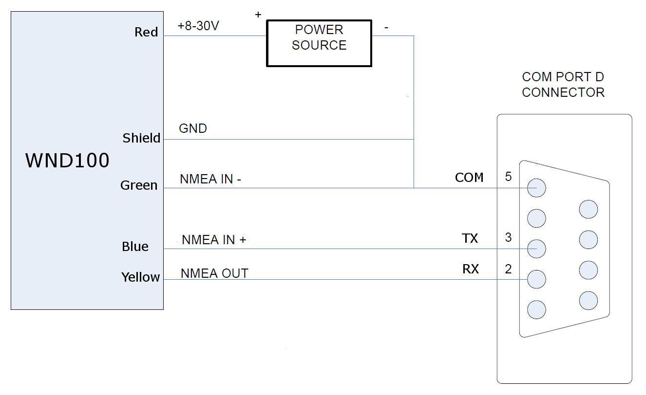
How to connect the WND100 to the WLN10/WLN30?
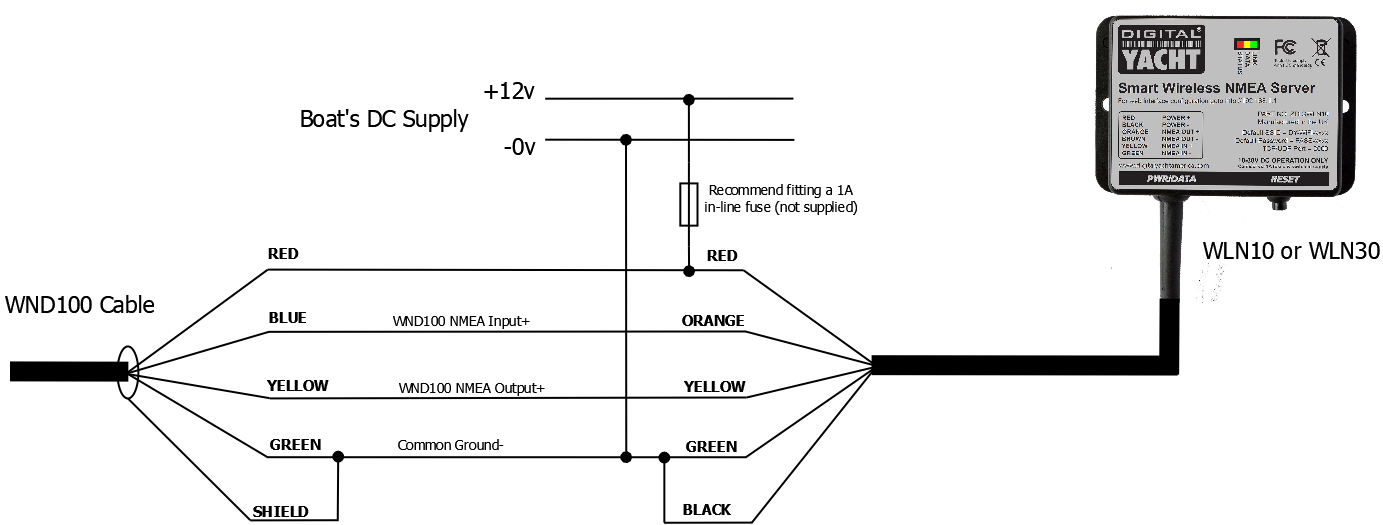
How to connect the WND100 to an NMEA 0183 equipment?
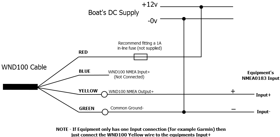
How to connect the WND100 to the Nasa Yacht Repeater?
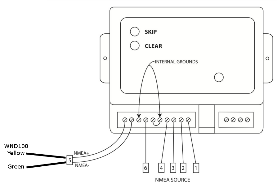
How to connect the WND100 to an NMEA 0183 to USB Adapter?
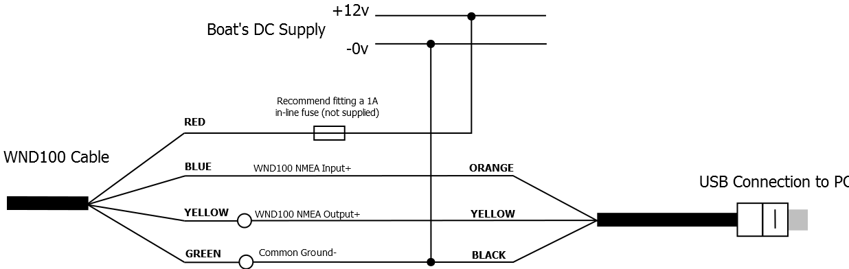
Connecting WND100 to iKonvert
HSC100
Calibration issues with HSC100 Fluxgate compass
The HSC100 should be accurate to +/- 3º through the full 360º. Any nearby ferrous items that cause a deflection/deviation in the local magnetic field around the HSC100 should be calibrated out by the calibration routine detailed in the manual and also shown here in an old video I made…
It is important that the calibration is carried out in the calmest of conditions possible, with minimum tide and wind effects.
BM100 & veKonvert
BM100 installation for Multi-Battery bank
You can monitor batteries in parallel (or series) with the BM-100 as long as the 500A continuous current rating is not exceeded.
The BM-100 will cope with sudden spikes in current well above 500A, for instance during engine starting.
You can also mix and match Victron kit with our veKonvert. We offer the BM-100 bundle, just so our customers can order a popular combination, but there is nothing to stop you buying any Victron Smart Shunt with ve.Direct interface and plugging it in to one of our veKonverts.
veKonvert will even work with Victron BMV units and MPPTs, it detects what it is connected to and changes its operation to suit.
How to setup and calibrate veKonvert for my boat’s battery system?
veKonvert connects to the SmartShunt via the veDirect interface. All calibration of the boat’s battery capacity etc is done via the Bluetooth interface integrated into the SmartShunt. Download the Victron app and follow the set up instructions included with the SmartShunt. There’s no calibration required on the veKonvert interface
Are larger shunts available for BM100?
As standard the BM100 includes a 500A shunt. 1000A and 2000A variants are available to special order. Please contact us.
veKonvert NMEA 2000 to VE.Direct Gateway – Compatibility List
veKonvert is compatible with the following Victron products…
- BMV -700
- BMV -702
- BMV -700H
- BMV-712 Smart
- BMV-710H Smart
- BMV-712 Smart Rev2
- SmartShunt 500A/50mV
- SmartShunt 1000A/50mV
- SmartShunt 2000A/50mV
- All MPPT Charge Controllers
NOTE – veKonvert is not compatible with Victron Chargers and Inverters. It should also not be plugged in to the VE.Direct interfaces of any Victron “Consumers” such as Multiplus, Quattro, Cerbo, etc.
NMEA to WiFi
WLN10 or WLN30 - NMEA 0183 to WiFi
What do the LED indicators mean on WLN10/30/NavLink2?
The following table explains the meaning of the WLN10/WLN30/Navlink2 LEDs:
| Condition | Red LED | Yellow LED | Green LED |
| ON (Solid) | Failed to Connect in STA Mode | HTTP or TCP Connection | |
| Blink | AP Mode | Data | Wireless Connection |
| OFF | Connected in STA Mode | No Data | No Connection |
Cannot connect a device to the WLN NMEA Server
Things have moved on in the iPhone world since 2012 and a number of security updates and changes in the way this wireless data is handled have made some of our older wireless products incompatible without getting an update.
You can either send your WLN10HS back to us for an update which is 1hr labour £45 + VAT plus postage or we can offer you a special 30% discount price on our latest WLN10SM – https://digitalyacht.co.uk/product/wln10sm/
Contact us at sales@digitalyacht.co.uk for a 30% discount code, including your proof of purchase and return the WLN10HS to us by following this FAQ: https://support.digitalyacht.co.uk/question/returning-a-product-to-our-uk-office-for-service/
How to update the built-in web interface?
The WLN10, WLN30 & NavLink2 have a built-in web interface. We have released a new web interface as well as some new functionalities. You can now filter the NMEA data and untick specific NMEA sentences which may create conflicts with some apps or software.
You can also choose a specific mode for the product, for instance, you can choose the AIS mode to only send AIS and GPS data to get a better result with an app that can only accept AIS & GPS data, such as Navionics.
The data monitor has also been improved and it is now easier to save the data. You can also choose to merge the product to an existing WiFi network and this functionality has also been enhanced to make it easier.
This video explains how to update the built-in web interface.
How to update the WLN10/30 firmware?
Since the WLN10SM unit was originally released we have released a few firmware updates to improve performance and add features. The latest version is V1.47 and we would recommend this update to anyone who has an earlier version of firmware on their unit – you can see the version number in the footer of the WLN10SM’s main web page.
The firmware update can be downloaded by clicking here.
IMPORTANT NOTE – the file you download is a compressed ZIP file, make sure you extract the binary (.bin) file inside and upload this file not the ZIP file, otherwise you could “brick” your WLN10SM and it will need to come back to Digital Yacht for repair (not under warranty).
We have tried to make the firmware update process as easy as possible on this new WLN10SM model and everything is done through the unit’s built-in web interface. To make things even easier, we have produced a short video of the process…
What’s the WiFi network password?
By default, NMEA to WiFi server’ creates a wireless Access Point (hotspot) on-board your boat. The Name (SSID) of the Access Point will be “NavLink2-xxxx” or “DY-WiFi-xxxx‘, etc, depending on the product you’ve purchased, where xxxx is the unique four digit code of your device.
To connect to the NMEA to WiFi server, you will need to scan for wireless networks, find and select it in the network list and then when prompted, enter the default WPA2 password, which is “PASS-xxxx”, where xxxx is the same, unique four digit code that is in the hotspot name.
For instance, if you have a WLN30 and the WiFi network name created is DY-WiFI-D4B7 then the WiFi network password is: PASS-D4B7
How to interface our WLN10/WLN30 to your navigation system?
Find out how to wire our NMEA to WiFi server WLN10/WLN30 to your navigation system (GPS, Chart plotter, Fish Finder, AIS, etc.) with this page.
I don’t receive NMEA data on an iPad/iPhone app
If you don’t receive the NMEA data on your iPad or iPhone, then you must follow this procedure:
1- Close all apps in the background or restart your device.
Always a good idea to shut down your iPad/iPhone device and then power it back up again, as this will close all background apps and ensure all of the right services are running. For more information: https://digitalyacht.net/2018/07/27/background-apps-stopping-wireless-nmea-transmission/
2- Local Network Settings
If you are using iOS 14 or higher, make sure the “Local Network” privacy settings are enabled for the app they want to use….
Go to Settings>Privacy>Local Network and make sure that the App is in the list and enabled….
3 – UDP or TCP?
Check what mode/protocol our product is set to, TCP or UDP (check product manual) and ensure that you set the same type of connection in the App. If the device is set to UDP and you try to use TCP in the App it will not work, both the device and app must be set to the same mode/protocol TCP or UDP. For TCP connections you need to enter an IP address of 192.168.1.1 and Port 2000, while for UDP you need to enter 0.0.0.0 and Port 2000, or if this fails try 192.168.1.1
4- App configured?
You must make sure that your app is configured. You should look at our section How to Configure Apps & Software to find out how to configure your navigation app.
5- GPS Settings
If you want the app to use the GPS data from the wireless connection, then go to Settings>Privacy>Location Services, on your iOS device and set the App to “Never” which will force the App to use the GPS position from the wireless connection, rather than try and use its internal GPS or even worse “Assisted GPS” if it is a Wi-Fi Only iPad.
What is the WiFi range/coverage of my product?
The Wi-Fi will typically footprint a boat up to 25m LOA. Contact us if you need a bigger footprint or have a steel or carbon vessel.
I have already a Wi-Fi router on board – can I join the product Wi-Fi to an existing network?
Yes! You can program this through the web interface so you just have one Wi-Fi network on board with our product linked directly to your other Wi-Fi network as a client.
This is explained in your product manual.
This works well as well with Furuno WiFi radar installations.
How to configure a navigation app or software?
We keep on our blog a list which explains how to configure all the popular navigation apps & software. This list explains how to configure a NMEA connection (UDP/TCP) on the app/software but also how to configure the AIS settings.
To see the list, please click here.
NavLink 2 - NMEA 2000 to WiFi
Setting up NavLink2 with Starlink – same IP address issue.
The Starlink router does use the same IP address range as our NAVLink2, BUT by default NAVLink2 creates its own wireless network “NAVLink-xxxx” which is the network you need to connect to, in order to configure it.
The ‘xxxx’, is a four digit code, unique to your unit, and the wireless password is “PASS-xxxx”. So if your unit is “NAVLink-A12B” then your wireless password will be “PASS-A12B” without the exclamation marks.
Once connected to NAVLink2, you can access its web interface at http://192.168.1.1 and go to the SETTINGS page. In the wireless network section, select STATION (STA) mode and tell NAVLink2 to access your Starlink network, rather than create its own.
Select the Starlink network in the Station SSID drop down box and enter whatever your Starlink’s wireless password is. Once you are happy, click the UPDATE SETTINGS button and the NAVLink2 will reboot and connect to Starlink rather than create its own network. Starlink will give NAVLink2 an IP Address in the 192.168.1.x range, but not 192.168.1.1
You can either look in the Starlink’s router web interface for what IP address it has given to NAVLink2 or you can use http://navlink2.local or http://navlink2.lan to bring up the NAVLink2 web interface and you can see what IP address it got in the SETTINGS page.
However, if you use UDP protocol, instead of TCP, on whatever Apps you want to use with NAVLink2, then you do not need to know the NAVLink2’s IP address just enter 0.0.0.0 and Port 2000, in the App.
We don’t have a manual TCP/UDP selector switch as the latest firmware supports concurrent UDP and TCP connections (1x UDP and 3x TCP).
Just set the Navionics App to UDP, Hostname = 0.0.0.0 and Port = 2000 and it should work.
Make sure you have the Navionics App enabled for LOCAL NETWORK service in the SETTINGS>PRIVACY & SECURITY menu on the iPhone.
NavLink and Furuno DRS4W Radar
We have had a few of our dealers and customers successfully connect the Furuno DRS4W and our NAVLink2 together, so that you have one wireless network.
The Furuno DRS4W must be the wireless Access Point and you have to tell our NAVLink2 to connect to the Furuno wireless network in Station mode – this is configurable in the NAVLink2 web interface SETTINGS page.
When the NAVLink2 connects to the Furuno network, you will not know what IP address it has received, so it is important that you use UDP mode for receiving the NAVLink2 data, as this works without knowing the IP address – you just enter 0.0.0.0 and Port 2000 in Navionics.
You should still be able to access the NAVLink2 web interface at http://navlink2.local
If you get in to any trouble and lose access to the NAVLink2, you can always factory reset the unit by pressing and holding its RESET push button for >10 seconds. This will put it back to its default Access Point mode and you can try again.
WIMWV instead of MWV from wind sensor
All NMEA 0183 sentences start with $XX which is called the “Talker ID” and identifies what type of product the data is coming from such as WI = Wind Instrument, II = Integrated Instruments, SD = Depth Sounder, EC = Electronic Charting system, etc.
What do the LED indicators mean on WLN10/30/NavLink2?
The following table explains the meaning of the WLN10/WLN30/Navlink2 LEDs:
| Condition | Red LED | Yellow LED | Green LED |
| ON (Solid) | Failed to Connect in STA Mode | HTTP or TCP Connection | |
| Blink | AP Mode | Data | Wireless Connection |
| OFF | Connected in STA Mode | No Data | No Connection |
How can I transfer my NavLink UK Software over from an old computer to my new Mac?
Unfortunately it isn’t as simple as just downloading the app on the new Mac and transferring the data over. If you backup/transfer your old mac to a new one, sometimes the problem is that the charts are still locked to the old computer.
To transfer the data across, you will need to use the Mac OSX Terminal window.
You need to use a ‘command line’ command to clear out the corrupted charts directory on your new Mac.
1) Exit NavLink Uk on your Mac
2) Open Terminal on your Mac and enter:
rm -rf /Users/yourusername/Library/Containers/com.pocketmariner.seanav.gb.mac.dy/Data/Library/Application Support/NavLink UK/chartSets/gb/*
Replacing yourusername with the user name you use on your Mac
Or:-
rm -rf ~/Library/Containers/com.pocketmariner.seanav.gb.mac.dy/Data/Library/Application Support/NavLink UK/chartSets/gb/*
3) Then reopen NavLink UK
If you need any further support, please create a Support Ticket through this site.
Testing NMEA 2000 Network
If you have an old or spare NMEA 2000 cable kicking around in your “come in handy” box, then put it to good use and create your own NMEA 2000 Test Lead. Assuming your cable is a Male to Female cable, you can actually create two test leads from the same cable, by simply cutting it in half, stripping back the outer insulation and fitting the five wires inside (Red/White/Blue/Black/Shield) to a piece of terminal “chocolate” block – as shown below.
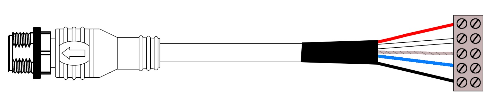
The Male Test Lead will actually be the most useful, as the majority of “back bone” connections are female, so you will be able to plug the Male Test lead in to any of these connections. The Female Test lead will be useful for connecting power to a “bus powered” NMEA 2000 device for firmware updating or configuration.
For the following tests we will be using the Male Test lead and a multi-meter to measure the NMEA 2000 Supply Voltage across the Red and Black power wires and to make sure the network is properly terminated by measuring the resistance between the Blue and White Data wires.
NMEA 2000 Supply Voltage Test
The NMEA 2000 network should be powered from a 12v supply and depending upon the number of devices on the network and the amount of power they take from the network, you may find voltage drops along the network. In extreme cases this can result in some devices not getting the proper 9.0v to 16.0v DC Supply voltage as specified in the NMEA 2000 specification.
You can use the NMEA 2000 Test lead to plug in to the network at various locations and test the supply voltage. In a well designed NMEA 2000 network the voltage drop should never be more than 1.5v. So if the supply voltage is 12.5v then you should never measure less than 11v at any point in the network.
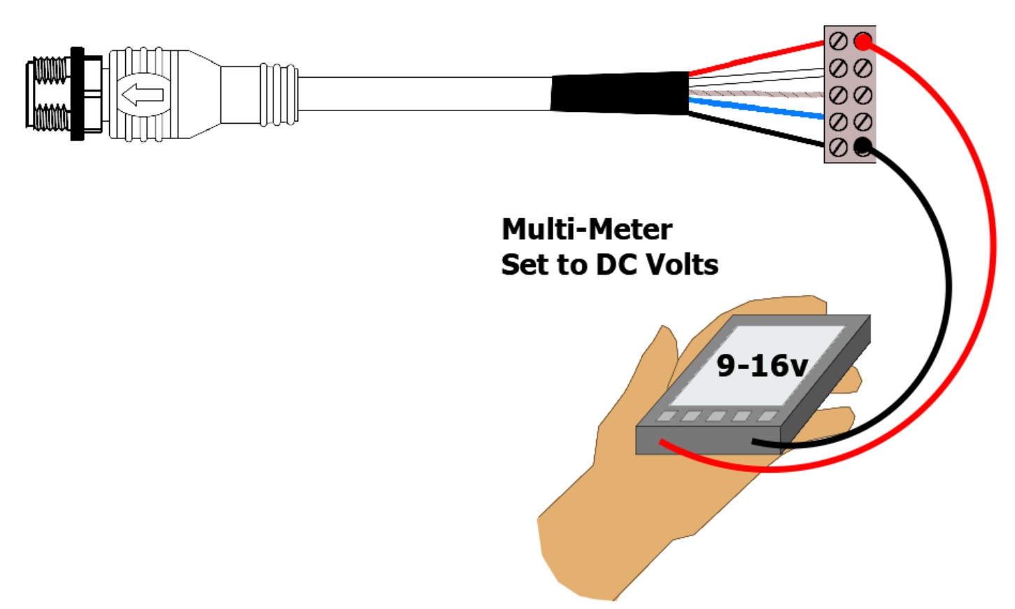
NMEA 2000 Correct Termination Test
The NMEA 2000 network should be properly terminated with a 120 Ohm resistor at each end of the backbone. No terminators, 1 terminator or more than two terminators can adversely affect the data signals and so it is important to test that your NMEA 2000 network is terminated correctly.
Two terminators, give a parallel resistance reading of 60 Ohms and this is what you should read. Plug the test lead in to any spare socket on the NMEA 2000 network and with the NMEA 2000 Network’s power removed, do a resistance test between the Blue and White Data wires of the NMEA 2000 test lead. You should measure 60 Ohms +/- 5%.
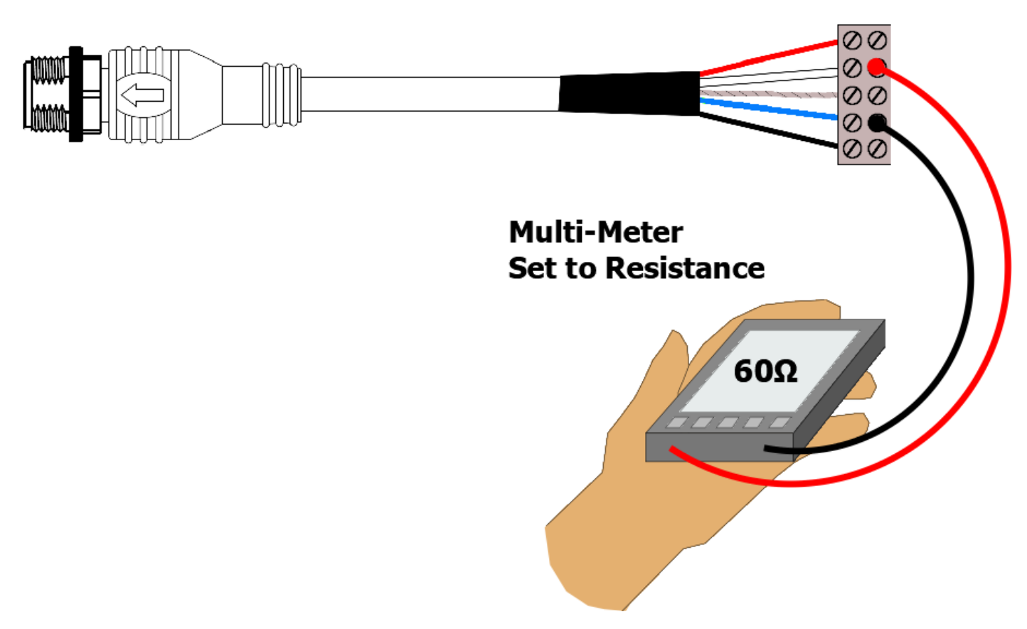
Using NAVDoctor to fully test an NMEA 2000 network
The two tests above are important basic tests to check the electrical integrity of your NMEA 2000 network, however with so many NMEA 2000 devices now being installed on boats, data and interoperability issues can also arise and if you wish to be able to more fully test and diagnose NMEA 2000 networks, our NAVDoctor NMEA 2000 Diagnostic tool is a good investment as this video will illustrate…
Navlink2 LED Flashing red
The flashing Red Error LED indicates that your NAVLink2 has quite an early version of firmware. As you can imagine, there are loads of different NMEA 2000 devices installed on boats, of varying age and firmware versions and since we released NAVLink2, we have come across quite a few “odd situations” where unexpected combinations of data have caused our “software watchdog” to detect an issue and restart the NAVLink2.
In each of these cases, we have had to release a firmware update for the NAVLink2, to fix the issue. We can update your unit to the very latest version (V2.70) for you free of charge, but you will need to post it back to our UK office following the procedure detailed in this FAQ: https://support.digitalyacht.co.uk/question/returning-a-product-to-our-uk-office-for-service/
I am a software developer, how can I learn more about implementing NMEA 2000 data in my software by using iKonvert/NAVLink2?
Our iKonvert/NAVLink2 gateways make implementing NMEA 2000 much easier, with no old, proprietary libraries, just a simple serial protocol that is published online at…
https://github.com/digitalyacht/iKonvert/wiki/4.-Serial-Protocol
The gateways take care of all of the complicated address claiming, network discovery and NMEA 2000 network management, simplifying and speeding up your software implementation. Here is a link to our iKonvert Developers Guide on GitHub…
https://github.com/digitalyacht/iKonvert
You will need a copy of the NMEA 2000 Appendix B in order to decode the NMEA 2000 PGN data, which is available from the NMEA organization.
If you have not already developed software to read and write NMEA 2000 data, then you might want to look at the open source CANBoat software, which supports our iKonvert as detailed in the CANBoat Wiki, see link below. The developer Kees, has over a number of years, reverse engineered the NMEA PGNs and the data is translated in to a more simple and open JSON format.
How to update the built-in web interface?
The WLN10, WLN30 & NavLink2 have a built-in web interface. We have released a new web interface as well as some new functionalities. You can now filter the NMEA data and untick specific NMEA sentences which may create conflicts with some apps or software.
You can also choose a specific mode for the product, for instance, you can choose the AIS mode to only send AIS and GPS data to get a better result with an app that can only accept AIS & GPS data, such as Navionics.
The data monitor has also been improved and it is now easier to save the data. You can also choose to merge the product to an existing WiFi network and this functionality has also been enhanced to make it easier.
This video explains how to update the built-in web interface.
How to update the NavLink2 firmware?
Since the NavLink2 unit was originally released we have released a few firmware updates to improve performance and add features. The latest version is V2.00 and we would recommend this update to anyone who has an earlier version of firmware on their unit – you can see the version number in the footer of the NavLink2’s main web page.
The firmware update file (NavLink2_V2-00_OTA.zip) can be downloaded from our GitHub repository by clicking here.
IMPORTANT NOTE – the file you download is a compressed ZIP file, make sure you extract the binary (.bin) file inside and upload this file, not the ZIP file, otherwise you could “brick” your NavLink2 and it will need to come back to Digital Yacht for repair (not under warranty).
We have tried to make the firmware update process as easy as possible on this new NavLink2 model and everything is done through the unit’s built-in web interface. To make things even easier, we have produced a short video of the process. This video explains how to update the WLN10’s web interface but it is the same process for the NavLink2:
What’s the WiFi network password?
By default, NMEA to WiFi server’ creates a wireless Access Point (hotspot) on-board your boat. The Name (SSID) of the Access Point will be “NavLink2-xxxx” or “DY-WiFi-xxxx‘, etc, depending on the product you’ve purchased, where xxxx is the unique four digit code of your device.
To connect to the NMEA to WiFi server, you will need to scan for wireless networks, find and select it in the network list and then when prompted, enter the default WPA2 password, which is “PASS-xxxx”, where xxxx is the same, unique four digit code that is in the hotspot name.
For instance, if you have a WLN30 and the WiFi network name created is DY-WiFI-D4B7 then the WiFi network password is: PASS-D4B7
I don’t receive NMEA data on an iPad/iPhone app
If you don’t receive the NMEA data on your iPad or iPhone, then you must follow this procedure:
1- Close all apps in the background or restart your device.
Always a good idea to shut down your iPad/iPhone device and then power it back up again, as this will close all background apps and ensure all of the right services are running. For more information: https://digitalyacht.net/2018/07/27/background-apps-stopping-wireless-nmea-transmission/
2- Local Network Settings
If you are using iOS 14 or higher, make sure the “Local Network” privacy settings are enabled for the app they want to use….
Go to Settings>Privacy>Local Network and make sure that the App is in the list and enabled….
3 – UDP or TCP?
Check what mode/protocol our product is set to, TCP or UDP (check product manual) and ensure that you set the same type of connection in the App. If the device is set to UDP and you try to use TCP in the App it will not work, both the device and app must be set to the same mode/protocol TCP or UDP. For TCP connections you need to enter an IP address of 192.168.1.1 and Port 2000, while for UDP you need to enter 0.0.0.0 and Port 2000, or if this fails try 192.168.1.1
4- App configured?
You must make sure that your app is configured. You should look at our section How to Configure Apps & Software to find out how to configure your navigation app.
5- GPS Settings
If you want the app to use the GPS data from the wireless connection, then go to Settings>Privacy>Location Services, on your iOS device and set the App to “Never” which will force the App to use the GPS position from the wireless connection, rather than try and use its internal GPS or even worse “Assisted GPS” if it is a Wi-Fi Only iPad.
What is the WiFi range/coverage of my product?
The Wi-Fi will typically footprint a boat up to 25m LOA. Contact us if you need a bigger footprint or have a steel or carbon vessel.
I have already a Wi-Fi router on board – can I join the product Wi-Fi to an existing network?
Yes! You can program this through the web interface so you just have one Wi-Fi network on board with our product linked directly to your other Wi-Fi network as a client.
This is explained in your product manual.
This works well as well with Furuno WiFi radar installations.
How to configure a navigation app or software?
We keep on our blog a list which explains how to configure all the popular navigation apps & software. This list explains how to configure a NMEA connection (UDP/TCP) on the app/software but also how to configure the AIS settings.
To see the list, please click here.
How to Log “RAW” NMEA 2000 Data on Latest NAVLInk2
Access the NAVLink 2 web interface and confirm it is the latest version as per the screen shot below….
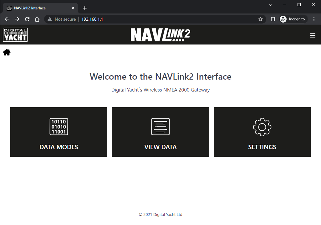
Select the “Data Modes” page, set the NMEA Mode to “15 – RAW Mode” and click the “Update Settings” button…
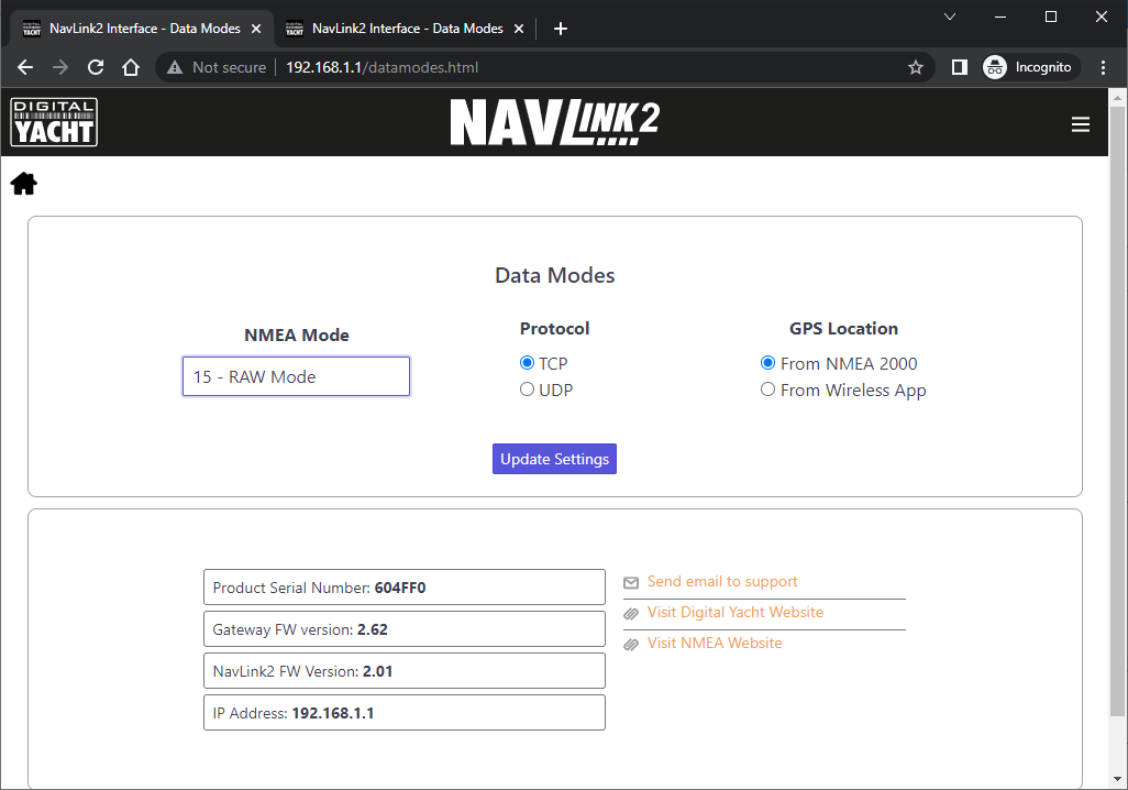
Ensure you get the Data Mode changed successfully message….
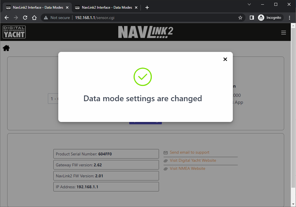
Now go to the “View Data” page and you will see data, similar to that shown below, scrolling down the screen…
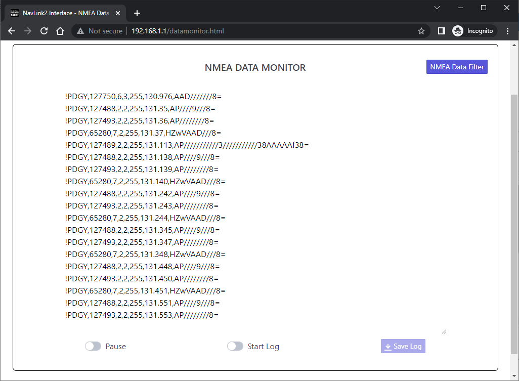
Now switch the “Start Log” button to ON and leave this page running for at least 15-20 minutes, so that we get a good selection of data. If there is a particular situation that causes a problem, please recreate this situation while the log is running.
Once you have collected enough data, switch the “Start Log” button to OFF and click the “Save Log” button which will now be active. Your browser will now download the log file in to your “Downloads” folder…
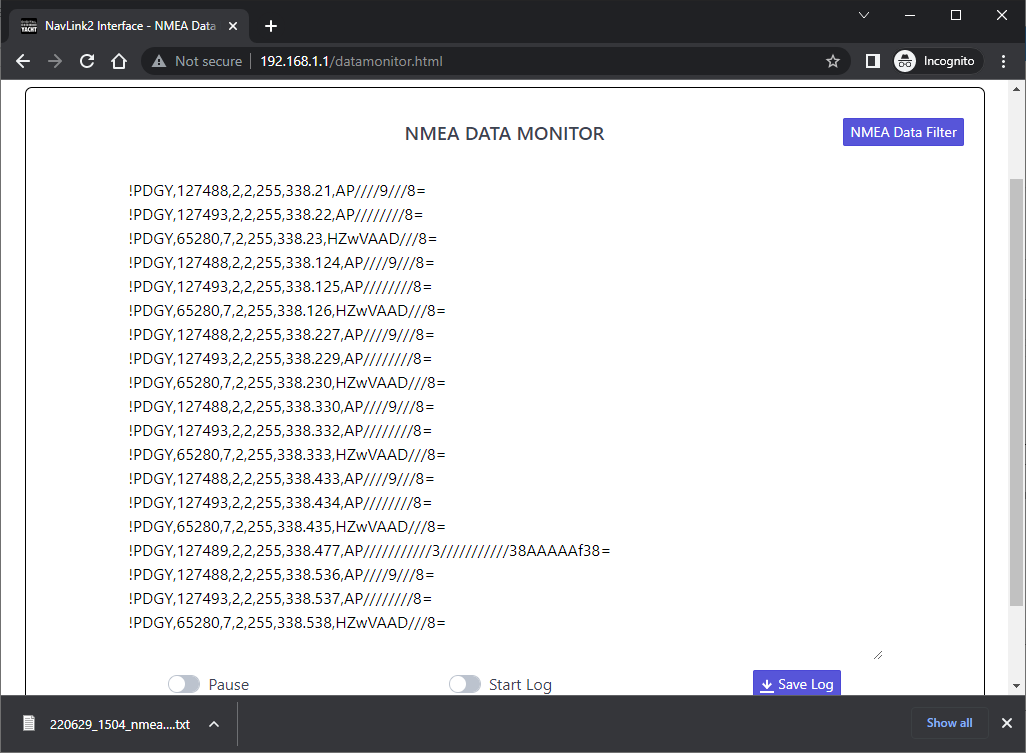
Please ZIP the text file and email to us for analysis.
ENGINELink
What’s the WiFi network password?
By default, NMEA to WiFi server’ creates a wireless Access Point (hotspot) on-board your boat. The Name (SSID) of the Access Point will be “NavLink2-xxxx” or “DY-WiFi-xxxx‘, etc, depending on the product you’ve purchased, where xxxx is the unique four digit code of your device.
To connect to the NMEA to WiFi server, you will need to scan for wireless networks, find and select it in the network list and then when prompted, enter the default WPA2 password, which is “PASS-xxxx”, where xxxx is the same, unique four digit code that is in the hotspot name.
For instance, if you have a WLN30 and the WiFi network name created is DY-WiFI-D4B7 then the WiFi network password is: PASS-D4B7
NMEA, SeaTalk & USB Interfaces
IKonvert - NMEA 2000 to NMEA 0183 or USB
iKonvert USB Gateway – Mouse goes Crazy!
NMEA 0183 data is often wrongly detected by Microsoft’s old “USB plug and play” detection software as a serial mouse. Here is an article I wrote on this back in 2014….still present in Windows 11 !!!
https://digitalyacht.net/2014/04/16/help-my-mouse-has-gone-crazy/
With an iKonvert USB it is pretty easy….just unplug the NMEA 2000 connection (not USB) when it happens and then go in and disable the Serial Mouse in the Device Manager.
Connecting a transponder to a chartplotter using iKonvert without an NMEA network.
NMEA 2000 is a great interfacing standard, BUT it does require a basic network to be in place, you cannot just plug the iKonvert in to the plotter. This simple guide that we created gives the key “things to know” about NMEA 2000….
https://support.digitalyacht.co.uk/how-to-create-an-nmea-2000-network/
Our NMEA 2000 Starter Kit gives you everything you need to connect the iKonvert and plotter together and even has a spare connection if you decide to add another NMEA 2000 device in the future.
How do I test if an iKonvert is faulty? – Supply Voltage Test
Our iKonverts are pretty “bulletproof” but of course it could be a component failure. A simple test of the NMEA 2000 supply voltage at the iKonvert PCB would be the best way to ascertain if it is a network issue of a faulty iKonvert.
Using a multimeter set to measure DC Voltage, please measure for the presence of a voltage between the two terminals in the below image. The voltage should be a nominal 12v, but it can be between 9v and 16v and the network should still operate correctly.
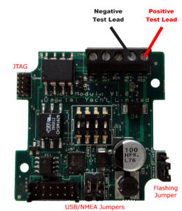
If there is no voltage at the iKonvert, then you have a network wiring issue, if there is a good 12v voltage, then the iKonvert will need to be returned to us for warranty repair/replacement.
Testing NMEA 2000 Network
If you have an old or spare NMEA 2000 cable kicking around in your “come in handy” box, then put it to good use and create your own NMEA 2000 Test Lead. Assuming your cable is a Male to Female cable, you can actually create two test leads from the same cable, by simply cutting it in half, stripping back the outer insulation and fitting the five wires inside (Red/White/Blue/Black/Shield) to a piece of terminal “chocolate” block – as shown below.
The Male Test Lead will actually be the most useful, as the majority of “back bone” connections are female, so you will be able to plug the Male Test lead in to any of these connections. The Female Test lead will be useful for connecting power to a “bus powered” NMEA 2000 device for firmware updating or configuration.
For the following tests we will be using the Male Test lead and a multi-meter to measure the NMEA 2000 Supply Voltage across the Red and Black power wires and to make sure the network is properly terminated by measuring the resistance between the Blue and White Data wires.
NMEA 2000 Supply Voltage Test
The NMEA 2000 network should be powered from a 12v supply and depending upon the number of devices on the network and the amount of power they take from the network, you may find voltage drops along the network. In extreme cases this can result in some devices not getting the proper 9.0v to 16.0v DC Supply voltage as specified in the NMEA 2000 specification.
You can use the NMEA 2000 Test lead to plug in to the network at various locations and test the supply voltage. In a well designed NMEA 2000 network the voltage drop should never be more than 1.5v. So if the supply voltage is 12.5v then you should never measure less than 11v at any point in the network.
NMEA 2000 Correct Termination Test
The NMEA 2000 network should be properly terminated with a 120 Ohm resistor at each end of the backbone. No terminators, 1 terminator or more than two terminators can adversely affect the data signals and so it is important to test that your NMEA 2000 network is terminated correctly.
Two terminators, give a parallel resistance reading of 60 Ohms and this is what you should read. Plug the test lead in to any spare socket on the NMEA 2000 network and with the NMEA 2000 Network’s power removed, do a resistance test between the Blue and White Data wires of the NMEA 2000 test lead. You should measure 60 Ohms +/- 5%.
Using NAVDoctor to fully test an NMEA 2000 network
The two tests above are important basic tests to check the electrical integrity of your NMEA 2000 network, however with so many NMEA 2000 devices now being installed on boats, data and interoperability issues can also arise and if you wish to be able to more fully test and diagnose NMEA 2000 networks, our NAVDoctor NMEA 2000 Diagnostic tool is a good investment as this video will illustrate…
Is iKonvert USB gateway compatible with LINUX or MAC OSX?
Yes, our iKonvert uses the popular FTDI serial to USB chip and the LINUX and MAC OSX drivers for this chip are included in the relevant operating system’s kernel. It should appear in the operating system as a serial device named “ttyUSB0” (or similar) when plugged in to a LINUX or MAC machine.
Can iKonvert USB gateway provide RAW NMEA 2000 data or does it just convert to NMEA 0183?
Our iKonvert can output converted NMEA 0183 sentences or the RAW NMEA 2000 data depending upon which mode it is set to (see user manual for more details). You can either set the mode by changing the four DIP switches inside the iKonvert or you can do this programmatically by sending a serial command to the iKonvert and the unit will stay in this mode even after a power cycle.
I am a software developer, how can I learn more about implementing NMEA 2000 data in my software by using iKonvert/NAVLink2?
Our iKonvert/NAVLink2 gateways make implementing NMEA 2000 much easier, with no old, proprietary libraries, just a simple serial protocol that is published online at…
https://github.com/digitalyacht/iKonvert/wiki/4.-Serial-Protocol
The gateways take care of all of the complicated address claiming, network discovery and NMEA 2000 network management, simplifying and speeding up your software implementation. Here is a link to our iKonvert Developers Guide on GitHub…
https://github.com/digitalyacht/iKonvert
You will need a copy of the NMEA 2000 Appendix B in order to decode the NMEA 2000 PGN data, which is available from the NMEA organization.
If you have not already developed software to read and write NMEA 2000 data, then you might want to look at the open source CANBoat software, which supports our iKonvert as detailed in the CANBoat Wiki, see link below. The developer Kees, has over a number of years, reverse engineered the NMEA PGNs and the data is translated in to a more simple and open JSON format.
Does the iKonvert have an autopilot mode?
Yes since V2.47 (end of 2020) our iKonverts have had two autopilot modes which the user can select using the DIP switches.
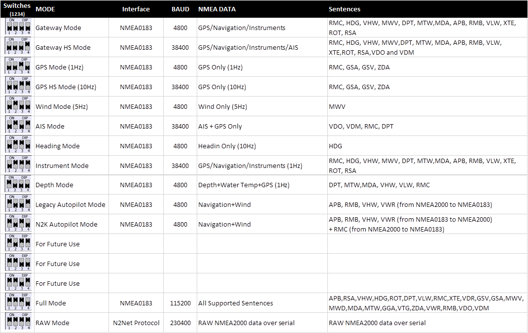
How to update the iKonvert USB?
Since Q1/2020, iKonvert has had a number of updates and if you would like to update the firmware, this FAQ will explain the procedure.
Please download a Tech Note detailing how to update the iKonvert and you have the USB version so connection to the PC is easy. Please note the additional step for iKonvert users and the Command Reference Application that they mention can be downloaded from our GitHub developers site….
https://github.com/digitalyacht/iKonvert
You can also get the V2.62 firmware from this GitHub site as well – remember to unzip it.
Connecting WindSense to an iKonvert
Connecting iKonvert to the GPS160
Connecting iKonvert to a NMEA0183 Chartplotter
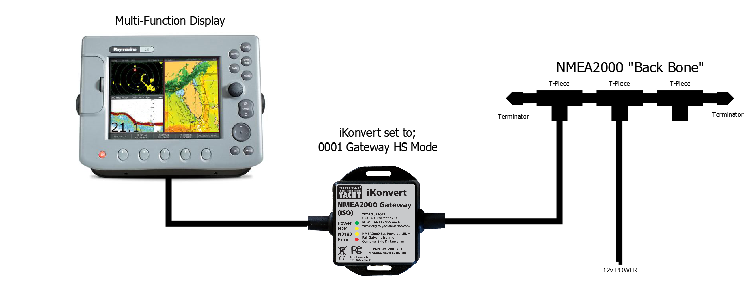
Connecting WND100 to iKonvert
NAVAlert
Updating the NavAlert firmware v1.0.7
Here is the V1.0.7 update for your NAVAlert.
Inside the ZIP file are two binary files, please extract the two files to an easy to access location on your computer. You will need to repeat the update process for each file.
Wirelessly connect to the NAVAlert and bring up the web interface at http://navalert.local or http://192.168.1.1
Goto the SETTINGS page and scroll down till you see the Firmware Update section. Click the Choose File button and browse your computer to find the binary file – NAVAlert_OTA_V1_07F.bin
It is very important that you upload the file that ends in F first and the file that ends in S second.
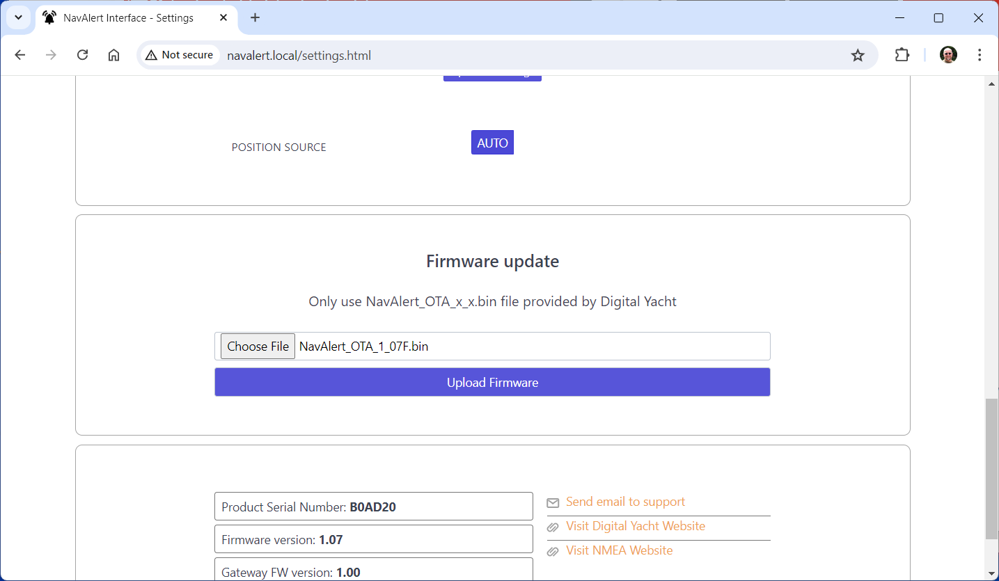
Once you have selected the correct file, click the Upload Firmware button and wait for the progress bar to move across the screen to 100%. An “Update Successful” pop-up will appear and the NAVAlert will reboot.
Wait 10 seconds and then press and hold the Reset button on the NAVAlert for >10 seconds (I normally give it 15 secs to be sure). Release the reset button and the NAVAlert will factory reset and reboot.
Reconnect wirelessly to the NAVAlert and repeat the process again for the second binary file – NAVAlert_OTA_V1_07S.bin
After you have finished uploading the second file and doing another factory reset – just for good luck – your NAVAlert will have the new 4GC/4GX/5GX/Littoral Link selection. Select the 4GXtream, enter your mobile number, press the Set Phone Number button and then click the Send Test SMS button.
Your mobile should receive an SMS test message and everything is working correctly.
Testing and Configuring the NAVAlert SMS Feature with 4G/5G Xtream
On the router, in Advanced mode go to SERVICES>MOBILE UTILITIES>SMS GATEWAY and check if there is a Username setup called NAVAlert….
If there is not, then create one and if there is, please set the Password to Alert123 in both boxes and click the SAVE&APPLY button.
Now open a new browser window and copy and paste the following link into the Address bar….
You should see an OK page appear and after a few seconds receive an SMS on your mobile….ignore my IP address and Mobile number which are different to yours.
This proves that the 4GXtream is configured OK for SMS.
Now let us turn our attention to the NAVAlert.
Please can you enter your mobile number pre-fixed with your country code i.e. 0033617812887 in the NAVAlert SMS field. If you have a button just to select 4GConnect or 4GXtream, then you do not have the latest firmware. You can either update your NAVAlert unit’s firmware, I will need to send this to you tomorrow as our developer is out of the office today, or you can go back to the SMS Gateway page on the 4GXtream and change the password of the NAVAlert Username to the original password = Alert and then click the Send Test SMS button.
What’s the WiFi network password?
By default, NMEA to WiFi server’ creates a wireless Access Point (hotspot) on-board your boat. The Name (SSID) of the Access Point will be “NavLink2-xxxx” or “DY-WiFi-xxxx‘, etc, depending on the product you’ve purchased, where xxxx is the unique four digit code of your device.
To connect to the NMEA to WiFi server, you will need to scan for wireless networks, find and select it in the network list and then when prompted, enter the default WPA2 password, which is “PASS-xxxx”, where xxxx is the same, unique four digit code that is in the hotspot name.
For instance, if you have a WLN30 and the WiFi network name created is DY-WiFI-D4B7 then the WiFi network password is: PASS-D4B7
NAVDoctor
Why can’t I stay connected to the NavDoctor?
Our NAVDoctor’s wireless interface is stable and you shouldn’t have a problem scanning, finding and connecting to it, but as it is a wireless device, rather than a wireless network router connected to the internet, some operating systems will sometimes disconnect and try and connect to a known wireless network that has internet connection.
In Android, because of the large number of different phone manufacturers, it is difficult to give an exact answer, but when you connect to the NAVDoctor, you should see a pop-up that says something similar to “Network has no internet, stay connected?” and you need to select whatever option to stay connected. If you have already connected to the NAVDoctor and this pop-up does not appear, then you need to goto Settings>WiFi>Menu/Advanced and look for a setting like “Check for Internet” or “Auto Network Switch” and these should be disabled. Also it might be best to temporarily turn off Mobile data so that your phone does not revert to 4G.
For Windows, in the NAVDoctor wireless network option, I would select “Forget this network” and then reconnect and make sure you tick “Connect Automatically”.
So many wireless devices exist now and many use the 192.168.1.1 IP address that NAVDoctor uses. For this reason, it is very common for your web browser to have stored “cached” data, code and images from other 192.168.1.1 web interfaces and this can cause issues when you try to display NAVDoctor – you end up with some old data from another device and some new data from NAVDoctor. For this reason, I always recommend using a “Private” or “Incognito” browser window which makes the browser behave as if you have never seen the NAVDoctor web interface before and loads everything from fresh.
Also our NAVDoctor is passing a lot of data to the browser and it can only cope with one browser session at a time, so make sure you do not have multiple devices connected or multiple tabs open on the same device.
If after trying the above tips, you aren’t seeing better operation, please get in contact via our support system, including as much information as you can, and we will do our best to get you back up and running smoothly.
What’s the WiFi network password?
By default, NMEA to WiFi server’ creates a wireless Access Point (hotspot) on-board your boat. The Name (SSID) of the Access Point will be “NavLink2-xxxx” or “DY-WiFi-xxxx‘, etc, depending on the product you’ve purchased, where xxxx is the unique four digit code of your device.
To connect to the NMEA to WiFi server, you will need to scan for wireless networks, find and select it in the network list and then when prompted, enter the default WPA2 password, which is “PASS-xxxx”, where xxxx is the same, unique four digit code that is in the hotspot name.
For instance, if you have a WLN30 and the WiFi network name created is DY-WiFI-D4B7 then the WiFi network password is: PASS-D4B7
N2K Protect
What’s the WiFi network password?
By default, NMEA to WiFi server’ creates a wireless Access Point (hotspot) on-board your boat. The Name (SSID) of the Access Point will be “NavLink2-xxxx” or “DY-WiFi-xxxx‘, etc, depending on the product you’ve purchased, where xxxx is the unique four digit code of your device.
To connect to the NMEA to WiFi server, you will need to scan for wireless networks, find and select it in the network list and then when prompted, enter the default WPA2 password, which is “PASS-xxxx”, where xxxx is the same, unique four digit code that is in the hotspot name.
For instance, if you have a WLN30 and the WiFi network name created is DY-WiFI-D4B7 then the WiFi network password is: PASS-D4B7
NjordLink
How to connect NjordLink to your boat’s network?
What is the password for my NjordLINK?
By default, Njordlink creates a wireless Access Point (hotspot) on-board your boat. The Name (SSID) of the Access Point will be “Njordlink-xxxx”, where xxxx is the unique four digit code of your device.
To connect to the Njordlink WiFi, you will need to scan for wireless networks, find and select it in the network list and then when prompted, enter the default WPA2 password, which is “PASS-xxxx”, where xxxx is the same, unique four digit code that is in the hotspot name.
For instance, if the WiFi network name created is Njordlink-D4B7 then the WiFi network password is: PASS-D4B7
As a boatbuilder, can you develop a custom app?
Yes – we can quickly and affordably develop a custom app. You can decide on how data is displayed and how to work with historical data for analysis. Contact njord@digitalyachtamerica.com
How can I become a developer?
Building apps with Njord cloud is easy using free APIs and scripts to quickly parse and query data. Contact njord@digitalyachtamerica.com and get involved in our webinars online.
Do I need internet connectivity for NjordLINK to function?
Yes – NjordLINK has to deliver the boat data to the cloud so you need an internet connection. It doesn’t consume much bandwidth and we automatically reconnect if the connection drops. A simple phone hotspot, wifi, 4G/5G connection or satellite service such as Starlink can be used.
How do I reset a NjordLINK?
Press and hold the reset button for 10 seconds. You’ll see the LEDs illuminate in sequence and then reverse the sequence. Release the reset button and NjordLINK will reboot and be returned to factory settings.
Is my data secure?
Yes. NjordLINK uses secure end to end encryption and you can decide who has access to your data online.
Where should I install NjordLINK?
NjordLINK requires a NMEA 2000 connection and also needs to wirelessly link to the boat’s internet network so position close to the internet router in a protected area.
LANLink - NMEA to Ethernet
NMEA LANlink to Ethernet cannot see each other on the network?
You need to setup a data link between the two LANLinks, as this will not happen automatically.
We recommend using a TCP connection between the LANLinks, this is much more reliable and a proper socket connection is created that you can see in the LANLink Status page, where as UDP is just a broadcast with no status or packet checking.
Setup the LANLink, connected to whichever device is outputting NMEA 0183, as a TCP server with a unique fixed IP address outside of the router’s DHCP range. Then set the other LANLink to be a TCP Client also with a unique fixed IP address outside of the router’s DHCP range. This ensures that the two LANLinks always have the same IP addresses even if the network changes and new DHCP leases are issued with different IP addresses.
Set the LANLink in TCP Client mode to connect to the IP address of the LANLink in TCP Server mode and make sure they are both set to the same Port – We suggest leaving this as the default Port 2000.
You should be able to see in the Status page of the TCP Server LANLink that the other LANLink has connected to it and see the data counter increase.
Any other devices on the network that have a TCP Client terminal program like Tera Term or PuTTY, should also be able to connect to the LANLink TCP Server and see the NMEA 0183 data being transmitted.
How to reset LanLink
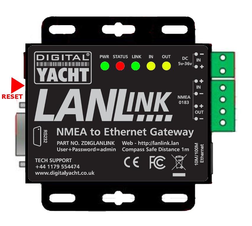
A reset is done by pressing and holding the small, recessed, push button on the side of the LANLink unit – next to the DC Jack socket. If this is pressed for between 5secs and 15secs while the unit is powered up, it will revert back to the Ethernet module’s defaults.
How to set LANLink to its default configuration
You first need to do a factory Reset again (Push and Hold Reset Switch for min 5sec and max 15sec) so the LANLink goes back to having a fixed IP address of 192.168.0.7 (255.255.255.0).
Plug the LANLink in to a PC/Mac and set the computer’s Ethernet port to a fixed IP address of 192.168.0.1 (255.255.255.0). Then you should be able to access the LANLink at http://192.168.0.7 and set it up with the default settings that we apply during production/test.
Here are a set of screen shots showing the defaults…
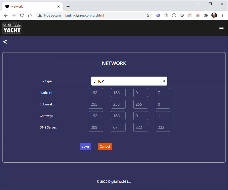
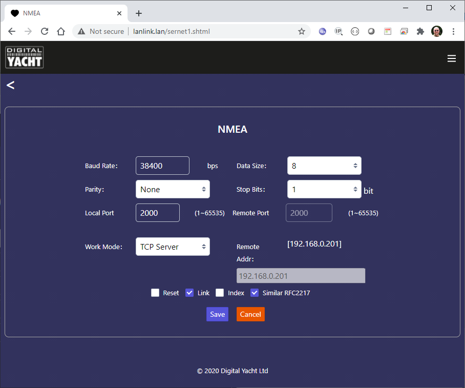
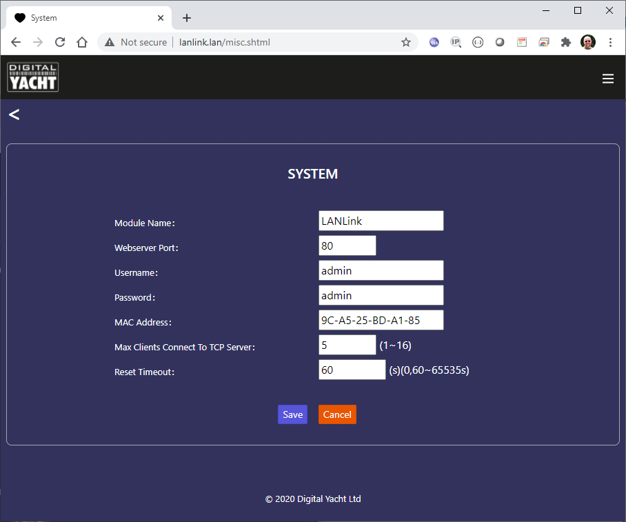
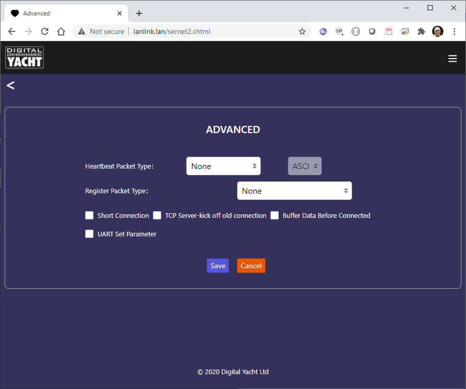
After setting up and saving all of the defaults, you should be able to power cycle the LANLink and plug it in to a normal Home/Office network that works on DHCP. The LANLink should get an IP address from the network router and you should be able to access it at its hostname URL of…
http://lanlink
How to run a DHCP server on PC using LANLink
To temporarily turn your laptop in to a DHCP server, the easiest and simplest way to do this, is using a free program called TFTP64 (Tiny FTP server). You can download this tool from…
https://digitalyachtamerica.com/download/tftp-zip/
Inside the ZIP file are two TFTP programs, and you want to use the TFTP64 one.
With your PC’s Ethernet LAN adaptor set to get an IP address automatically (default for Windows), run TFTP64 and go to the DHCP tab. Click the Settings button and enter the details below…
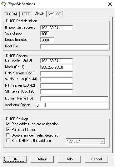
Click OK and you will be taken back to the DHCP server tab and you should see that your PC has been allocated 192.168.64.1 and when you plug in the LANLink, it should get 192.168.64.2
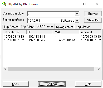
Now you can open a browser and go to http://192.168.64.2 to bring up the LANLink web interface. You will get the pop-up login box displayed and then once you have logged in using admin for the username and password, you will be all set to configure the LANLink as required.
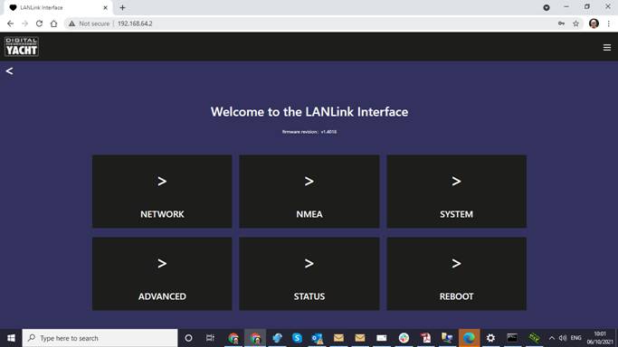
LANLink Network Behaviour
“Out of the box”, our LANLink will default to getting an IP address automatically from any network device it is connected to. Most Ethernet networks have a router that is responsible for providing all of the wireless and wired devices on the network with IP addresses via the “Dynamic Host Configuration Protocol” (DHCP).
The only slight problem with this approach, is that you do not know what IP address the router has given the LANLink. There are a number of ways to work around this….
1) Access the LANLink web interface using its domain URL http://lanlink and then go to the “Status” page to find its IP address – 192.168.42.207 in the example below…
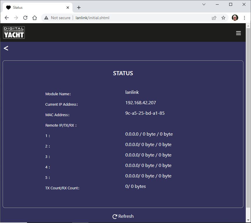
2) Log in to the routers web interface and look at its DHCP Client list, where it lists all of the devices connected to it and the IP addresses it has given them. Each router is slightly different in how you access this or what the list looks like, but here is an example…
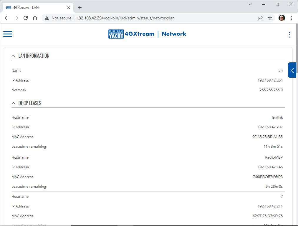
3) Use a 3rd Party Network analysis tool to discover what IP address the LANLink has. I use one called Fing, which is pretty good and is available for free on iOS, Android, Windows and Mac.
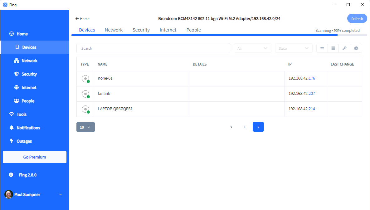
The only thing that cause an issue, is if the unit has been reset. A reset is done by pressing and holding the small, recessed, push button on the side of the LANLink unit – next to the DC Jack socket. If this is pressed for between 5secs and 15secs while the unit is powered up, it will revert back to the Ethernet module’s defaults.
If you cannot find the IP address using either of the three methods above, then we have to assume that the unit is reset and now it will be necessary to connect the LANLink directly to a PC/Mac via a normal Ethernet network cable and set the PC to have a manual (fixed) IP address of 192.168.0.1 and subnet 255.255.255.0. Now you should be able to access the LANLink at http://192.168.0.7
If this is the case and the LANLink has been reset and you can access it on this fixed IP address, check the FAQ above with the default settings you will need to set.
NMEA 0183 to USB Adapter
Using Tera Term to View NMEA 0183 Data
You can view the NMEA 0183 data coming out of one of our USB devices using Tera Term, a free Windows terminal program, which can be downloaded from the link below…
https://osdn.net/projects/ttssh2/releases/
Just select the latest EXE installer version and once downloaded, double click on the file to install TeraTerm. You only need the main program, not all of the extra plugins and language extensions, so untick everything else as shown below….
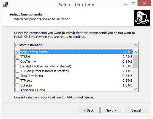
Once Tera Term is installed, you need to confirm what COM port Windows has allocated to your device’s USB interface. It was COM3 on our PC, but it might be a different number on yours and the best way to confirm is to open “Device Manager” on your Windows PC, go to the “Ports (COM & LPT)” section and see what is listed there.
You should see at least one COM port listed and if you then unplug your USB to NMEA cable and see which entry disappears, this will confirm which COM port it is.
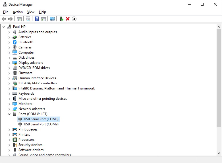
Now run Tera Term and create a new serial connection to the COM port number of your USB to NMEA cable…
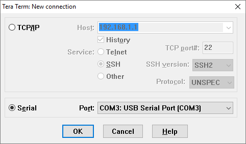
Click “OK” and you will see a terminal window appear, which may or may not have any NMEA 0183 data displayed in it.
In the image above, you can see strange characters scrolling down the screen, which usually indicates a wrong baud rate (data speed) setting. Click on Setup>Serial Port and change the baud rate to either 4800 baud (standard for GPS, Instruments, etc.) or 38400 baud (high speed setting for AIS or multiplexers).
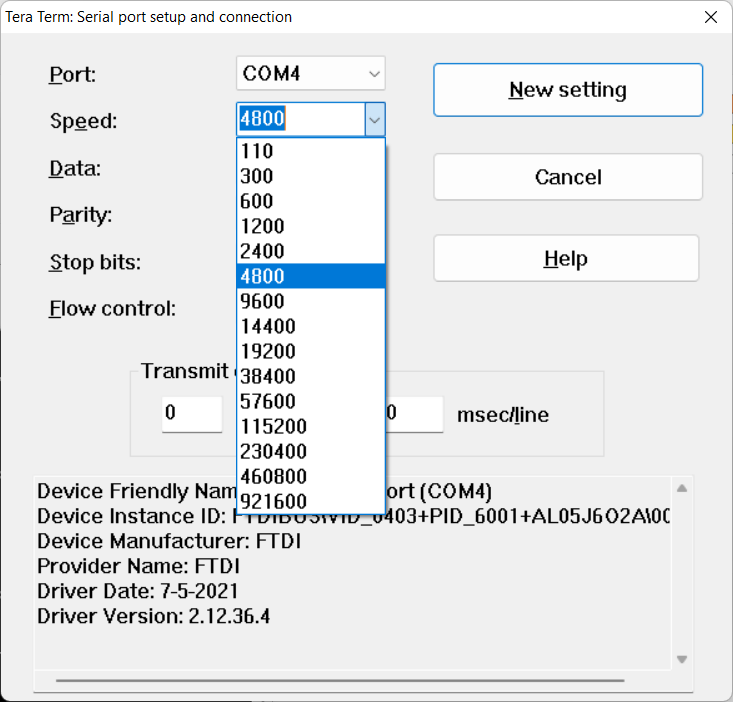
Now when y0u click the “New Setting” button the data should be much better formatted with one NMEA 0183 sentence per line…
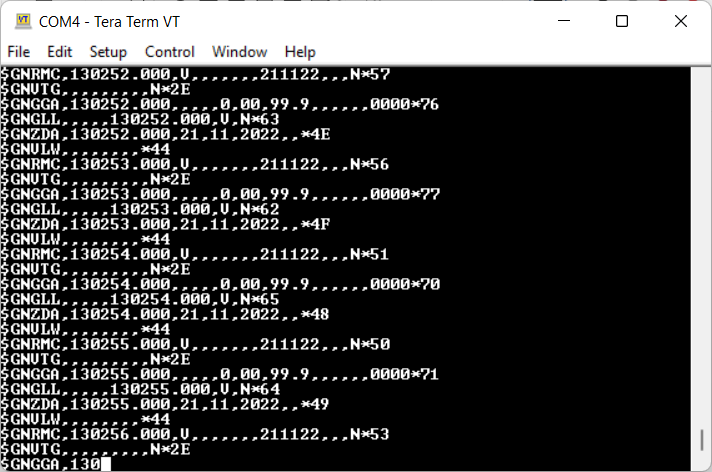
To understand the data that you are seeing, you will need to search online for information on NMEA 0183 or consider buying the latest NMEA 0183 specification from the NMEA organisation at https://nmea.org
NMEA 0183 to USB adapter Testing
You can test the USB to NMEA cable by doing a “Loopback” test as follows…
You will need a Windows PC to and a copy of TeraTerm which is free to download from the link below…
https://osdn.net/projects/ttssh2/releases/
Just select the latest EXE installer version and once downloaded, double click on the file to install TeraTerm. You only need the main program, not all of the extra plugins and language extensions, so untick everything else as shown below….
Once Tera Term is installed, we need to confirm what COM port Windows has allocated to your USB to NMEA Cable. It was COM3 on my PC, but it might be a different number on yours and the best way to confirm is to open “Device Manager” on your Windows PC, go to the “Ports (COM & LPT)” section and see what is listed there.
You should see at least one COM port listed and if you then unplug your USB to NMEA cable and see which entry disappears, this will confirm which COM port it is.
Now run Tera Term and create a new serial connection to the COM port number of your USB to NMEA cable…
Click “OK” and you will see a terminal window appear. Now you need to create the “Loop back” by physically connecting the Yellow (RX) and Orange (TX) wires together which loops the data back on itself.
Now when you type any characters on the keyboard, you should see them appear in the Window and at the same time, each press of the keyboard will make the Red and Green LEDs in the USB connector flash.
If for each key press you get two matching characters appear (see above), don’t worry it just means that the “Local Echo” tick box in the Tera Term “Setup>Terminal” options is enabled…
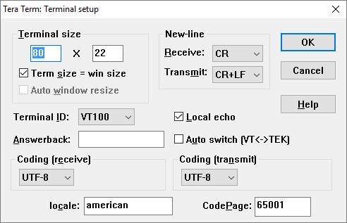
NMEA 0183 to USB Adaptor Driver Installation
In most cases, if your computer is connected to the internet, when you plug the USB to NMEA adaptor in to a spare USB socket, the driver should be automatically installed on Windows/MAC OSX/LINUX.
Sometimes with Windows PCs, it is necessary to manually install the USB drivers which can be downloaded from here….
https://digitalyachtamerica.com/download/usb-nmea-adaptor-drivers-v2-12-28-for-windows-exe/
This will download a zip file that when you double click will show a single exe file…
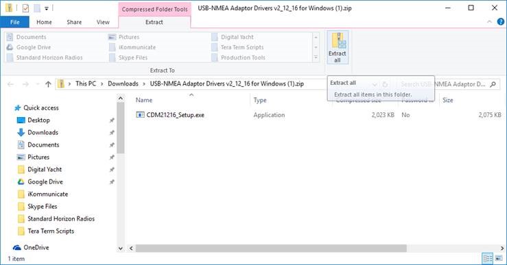
Extract this EXE file and then right click on it and select “Run as administrator”…
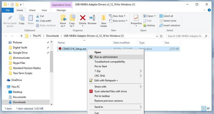
Now plug in the USB cable and check in Device Manager that the USB to NMEA adaptor has been successfully allocated a COM port number in the “Ports (COM&LPT)” section – COM6 in the example below.
This is the COM Port number you will need to select in your navigation software.
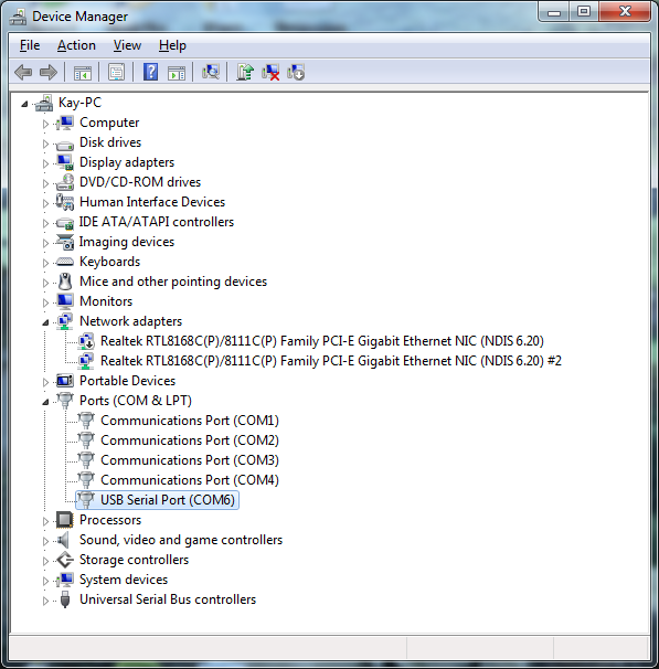
iKommunicate
iKommunicate Gateway – Upgrade Program
We started developing iKommunicate back in 2015 to be the first commercial Signal K (Marine Open Data Format) on the market, as part of a successful Kickstarter Campaign. Signal K was at a very early stage of its development and had not even reached a stable V1.00.
Digital Yacht were the first commercial company to support Signal K and we helped the core team of open source developers to make the final push to release Signal K V1.00, actively working on the specification, branding and website development.
Unfortunately, this level of involvement was unsustainable and when one of our iKommunicate Engineers retired and another went off to start his own business, we had to “freeze” further development. iKommunicate is still a good gateway product and for many people who just want a unit that works but do not want the latest cutting edge functionality, it is a good choice. It is also a very good gateway for the popular Rosepoint Coastal Explorer software for PCs.
In recent years, we have had reports that a change in the way the Signal K server initiates a websocket connection has broken compatibility with iKommunicate which uses the V1.00 Signal K APIs. We believe there is a work around to this, but you would need to contact Teppo Kurki or Scott Bender, on the core SK development team to discover what that is.
For anyone wanting to keep up with the cutting edge functionality of the latest Signal K developments, we have an upgrade program for all iKommunicate owners, that provides a 30% discount voucher for one of our iKonvert or NAVLink2 gateways. Both of these units are NMEA 2000 certified gateways which the Signal K developers have implemented and which work very well with the Signal K server…..
https://digitalyacht.net/2021/02/23/signal-k-opencpn-digital-yacht/
Please contact sales@digitalyacht.co.uk if you would like to know more about the upgrade program.
Add and/or change the PGN definitions in iKommunicate
Hi Paul,
We started developing iKommunicate back in 2015 and it was the first commercial product to support Signal K. Digital Yacht also helped with the final push to release Signal K V1.00, actively working on the specification, branding and website development.
Unfortunately, this level of involvement was unsustainable and when one of our iKommunicate Engineers retired and another went off to start his own business, we had to “freeze” further development. iKommunicate is still a good gateway product and for many people who just want a unit that works but do not want the latest cutting edge functionality, it is a good choice.
It is clear that you want more functionality than iKommunicate can really provide and I think you would be better off using Raspberry Pi type hardware, running the latest Open Source Signal K Server, being supplied NMEA 2000 data via one of our iKonverts or NAVLink2. Both of these units are NMEA 2000 certified gateways that the developers of CANBoat and CANBoatJS have implemented and which work very well with the Signal K server…..
https://digitalyacht.net/2021/02/23/signal-k-opencpn-digital-yacht/
You will then be able to access pretty much all of the data on the NMEA 2000 network and access it via HTTP RestAPIs.
How to factory reset an iKommunicate?
We know how much you like to tweak, change and fiddle with settings, but sometimes it can create problems and to ensure that you can recover your iKommunicate, we have devised a simple way to reset the unit back to its original factory defaults. Only the settings will be reset, any new software update will still be applied.
There are two methods to factory reset an iKommunicate.
- Manual Factory Reset. Click here to download the instruction.
- Factory Reset via Telnet. Click here to download the instruction.
SeaTalk Converter
Enable STALK Mode on a SeaTalk Converter
If you have the Seatalk to USB converter, then you can plug this straight in to a Windows, LINUX or Mac computer and use a Telnet Terminal type program to send this command. If you have the Seatalk to NMEA0183 converter, you need to use a NMEA 0183 to USB Adapter.
On a Mac we use CoolTerm which is freeware by Roger Meier…
https://freeware.the-meiers.org/
You need to make sure that CoolTerm is set to send CR+LF as the Enter (EOL) characters, as this is always used in NMEA 0183 systems to indicate the end of the sentence has been reached.
Then copy the command: $PDGY,STalk,On
And paste it into CoolTerm or any Telnet Terminal Type program and the mode should change.
How to update the SeaTalk converter firmware?
- If you have the Seatalk to USB converter, then you don’t need any extra cables
- If you have the Seatalk to NMEA 0183 converter then you will need an NMEA0183/RS422/RS232 to USB adaptor cable, but the procedure is the same.
- Please download the Tech Note that explains the procedure. It is the same procedure for our ST-NMEA, iKonvert and GPS160 products, that all have an STM32 micro.
- Also download the latest V2.08 firmware. This is a ZIP file which you will need to unzip and there is just one BIN file inside. This is the file that you upload to the ST-NMEA converter.
NMEA 2000 to BT
MOB Alert & NavAlarm
NMEA 2000 Cables
How to connect NMEA 2000 devices?
You cannot just plug two NMEA 2000 devices together with a suitable NMEA 2000 cable – they must be connected to a properly constructed NMEA 2000 network.
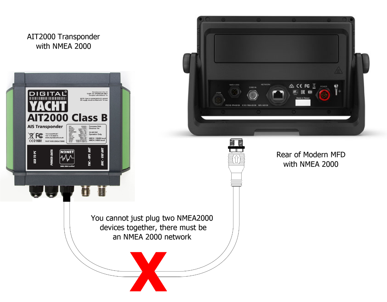
- Each device has an NMEA 2000 interface that must be powered from the network
- Some smaller low power devices, like sensors are also powered from the network
- There is a small cost in setting up the network, but future expansion is very easy
- An NMEA 2000 Starter Kit is a cost effective way to build a small, expandable network
Testing NMEA 2000 Network
If you have an old or spare NMEA 2000 cable kicking around in your “come in handy” box, then put it to good use and create your own NMEA 2000 Test Lead. Assuming your cable is a Male to Female cable, you can actually create two test leads from the same cable, by simply cutting it in half, stripping back the outer insulation and fitting the five wires inside (Red/White/Blue/Black/Shield) to a piece of terminal “chocolate” block – as shown below.
The Male Test Lead will actually be the most useful, as the majority of “back bone” connections are female, so you will be able to plug the Male Test lead in to any of these connections. The Female Test lead will be useful for connecting power to a “bus powered” NMEA 2000 device for firmware updating or configuration.
For the following tests we will be using the Male Test lead and a multi-meter to measure the NMEA 2000 Supply Voltage across the Red and Black power wires and to make sure the network is properly terminated by measuring the resistance between the Blue and White Data wires.
NMEA 2000 Supply Voltage Test
The NMEA 2000 network should be powered from a 12v supply and depending upon the number of devices on the network and the amount of power they take from the network, you may find voltage drops along the network. In extreme cases this can result in some devices not getting the proper 9.0v to 16.0v DC Supply voltage as specified in the NMEA 2000 specification.
You can use the NMEA 2000 Test lead to plug in to the network at various locations and test the supply voltage. In a well designed NMEA 2000 network the voltage drop should never be more than 1.5v. So if the supply voltage is 12.5v then you should never measure less than 11v at any point in the network.
NMEA 2000 Correct Termination Test
The NMEA 2000 network should be properly terminated with a 120 Ohm resistor at each end of the backbone. No terminators, 1 terminator or more than two terminators can adversely affect the data signals and so it is important to test that your NMEA 2000 network is terminated correctly.
Two terminators, give a parallel resistance reading of 60 Ohms and this is what you should read. Plug the test lead in to any spare socket on the NMEA 2000 network and with the NMEA 2000 Network’s power removed, do a resistance test between the Blue and White Data wires of the NMEA 2000 test lead. You should measure 60 Ohms +/- 5%.
Using NAVDoctor to fully test an NMEA 2000 network
The two tests above are important basic tests to check the electrical integrity of your NMEA 2000 network, however with so many NMEA 2000 devices now being installed on boats, data and interoperability issues can also arise and if you wish to be able to more fully test and diagnose NMEA 2000 networks, our NAVDoctor NMEA 2000 Diagnostic tool is a good investment as this video will illustrate…
Marine PC
Aqua Compact & Aqua Nav
Help my mouse has gone crazy!

- If you have ever taken a PC onboard a boat and connected it up to a GPS via a serial or USB port then the chances are that you will probably have seen the occasional “crazy mouse” behaviour that seems to affect so many marine PCs. The cursor will suddenly start to randomly move all over the screen, opening windows and clicking on things, as if possessed by some nautical demon !
- Well there is a very simple explanation for this phenomenon and it dates back to the good old Serial Port mouse that was popular on the first Windows PCs. It was the mouse with the large 9 pin D-Type connector on the end of the cable, that came out before the short lived PS2 connector mouse and the more recent USB mouse.
- These original Serial Port mice used a series of ASCII control signals that are very similar to those produced by a typical NMEA0183 interface on a modern GPS or chart Plotter. If the GPS or Plotter is turned on when the PC boots up, Windows detects the NMEA0183 signals, thinks it has an old Serial Mouse connected and loads up some very old driver software that then proceeds to move the cursor all over the place, opening and closing windows and generally behaving like a “crazy mouse”.
- All of the releases of Windows have suffered from this problem and even the very latest Windows 8.1 still has this old Serial Mouse detection software included and will go crazy in certain conditions. The good news is that it is pretty easy to fix, by going in to Device Manager and disabling (NOT uninstalling) the Serial Port Mouse. Digital Yacht have produced a Tech Note on how to fix the problem and a copy can be downloaded by clicking here.
What’s this orange Led on my PC?
That is the Hard Drive LED and flashes when there is disk activity.
My PC keeps turning off
Your PC may have gone in to power save mode and turned off the screen.
Make sure that you have set your PC’s Power Mode to High Performance and to make sure it will not power any peripherals down as detailed in the link below…
SmarterTrack
Windows Defender warning with SmarterTrack installation
The warning you are seeing when trying to run the SmarterTrack Setup file, is the standard Windows Defender warning that is displayed when you try to run a downloaded file from the internet…
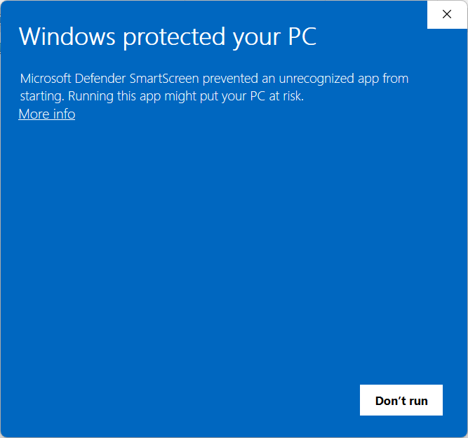
If you do not know the source or validity of the file then you would not want to run it, BUT as you know both of these things with our SmarterTrack software you should click the More Info link in the top left of the window. Now Windows will tell you a bit more about the file and give you the option to “Run anyway” by clicking the new button that has appeared…
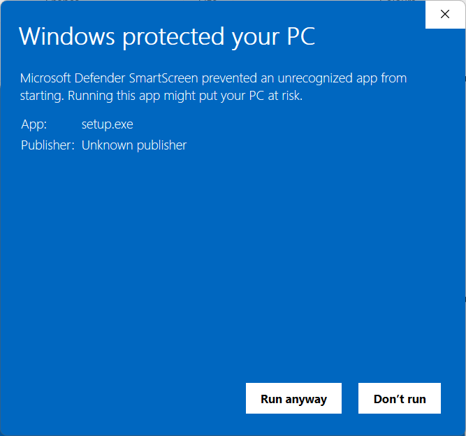
Clicking the “Run anyway” button will start the SmarterTrack installation and when complete, you should have SmarterTrack installed.
Please note that you need to be online to authorise the software with your license code and to install/copy your Navionics charts on to your PC’s hard drive.
I cannot Install Navionics Charts in SmarterTrack software
Our popular SmarterTrack Navigation Software uses Navionics charts, which you can copy from the Navionics Chart Cartridge on to a maximum of 5 PCs. Each PC must be online when you install the charts and SmarterTrack registers the PC on the Navionics charts server.
This mechanism has worked well for many years, but after the acquisition of Navionics by Garmin, a security audit indicated that a more secure HTTPS connection to the server should be used and Navionics updated their server.
Unfortunately, this also means that all SmarterTrack customers must update their copy of SmarterTrack before they can install any new charts. The good news is that the update is free of charge and can be downloaded from the link below….
General
Digital CD – Driver Software and Utilities
We’ve made the decision to not supply CDs containing driver software and utilities with products going forward. The CD drive has largely disappeared from PCs and Macs and most users are content downloading the very latest versions from our website. We’ve put together a download link below compiling the contents of our CD.
CDs also aren’t accepted in a single return stream recycling unit and to make 30 CDs consumes 2 cups of crude oil, 300 cubic feet of natural gas and 24 gallons of water, so the environment will thanks us all too.
Returning a Product to our French Office for Service
If we’ve ascertained that your items needs to come back to us for factory service/inspection, please complete and print the following Service Return Form and enclose it with the item.
Please note: Only return a product to us if it has been authorised by one of our advisors. Items that are returned without this completed service return form or authorisation will be delayed.
It’s important we receive as much information as possible, so please attach with the item any email correspondence you may have had with your advisor and include a detailed description of the fault.
All customers within the EU, should please return the unit to:
Digital Yacht Service.
12 Boulevard des Belges,
76000 Rouen,
FRANCE
If you’re returning a product from outside the EU, please put a value of GBP £10.00/ USD $14.00 / EUR €12.00 for the product and if requested by the freight company or postal service, use MARINE ELECTRONIC EQUIPMENT as a description and the commodity code 90148000.
The reason for return can be Product Service or Return for Repair.
If you are returning an AIS transponder for MMSI programming/reprogramming, please also complete this AIS PROGRAMMING form with vessel details. If you do not have Microsoft Word or a means of editing Word documents, please complete this PDF version.
We’ll look at your unit as quickly as possible and contact you with our findings.
Returning a product to our UK Office for Service
If we’ve ascertained that your items needs to come back to us for factory service/inspection, please complete and print the following Service Return Form and enclose it with the item.
It’s important we receive as much information as possible, so please attach with the item any email correspondence you may have had with your advisor and include a detailed description of the fault.
Please return the unit to:
DIGITAL YACHT SERVICE.
7 FARLEIGH COURT,
FLAX BOURTON,
BRISTOL
BS48 1UR
UNITED KINGDOM
If you’re returning a product from outside the UK, please put a value of GBP £10.00/ USD $14.00 / EUR €12.00 for the product and if requested by the freight company or postal service, use MARINE ELECTRONIC EQUIPMENT as a description and the commodity code 90148000.
The reason for return can be Product Service or Return for Repair. We recommend using USPS/Postal services if shipping from the US, as these are cheap and generally reliable.
If you are returning an AIS transponder for MMSI programming/reprogramming, please also complete this AIS PROGRAMMING form with vessel details. If you do not have Microsoft Word or a means of editing Word documents, please complete this PDF version.
We’ll look at your unit as quickly as possible and contact you with our findings.